H-11
FX Series PLC User's Manual - Data Communication Edition
Programming Communication
2 System Configuration and Selection
2.2 Applicable FX PLC and Communication Equipment
A
Common Items
B
N:N Network
C
Parallel Link
D
Computer Link
E
Inverter
Communication
F
Non-Protocol
Communication
(RS/RS2 Instruction)
G
Non-Protocol
Communication
(FX
2N
-232IF)
H
Programming
Communication
I
Remote
Maintenance
Apx.
Discontinued
models
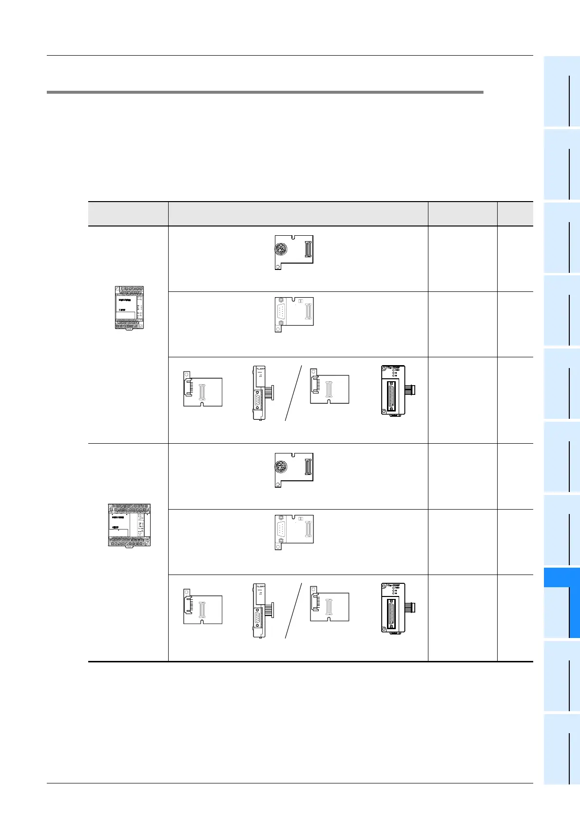
2.2 Applicable FX PLC and Communication Equipment
Select a communication equipment combination, and put a check mark in the "Check" column.
During selection, pay attention to the following:
-
In the table below, only the outside dimensions are different between the units shown in "FX
2NC
-232ADP/
FX
0N-
232ADP".
Select either one.
- Only one unit of communication equipment can be connected.
- In the FX
0, FX0S and FX0N Series, only the standard built-in port (8-pin MINI-DIN) is provided.
- In the FX
1, FX2(FX), and FX2C Series, only the standard built-in port (25-pin D-Sub type) is provided.
FX Series Communication equipment (option)
Total extension
distance
Check
FX
1S
Standard built-in
port (8-pin MINI-
DIN)
50 m
(164' 0")
15 m
(49' 2")
15 m
(49' 2")
FX
1N
Standard built-in
port (8-pin MINI-
DIN)
50 m
(164' 0")
15 m
(49' 2")
15 m
(49' 2")
FX
1N
-422-BD
(8-pin MINI-DIN)
FX
1N
-232-BD
(9-pin D-Sub)
FX
1N
-CNV-BD
+
FX
2NC
-232ADP
(9-pin D-Sub)
FX
0N
-232ADP
(25-pin D-Sub)
FX
1N
-CNV-BD
+
FX
1N
-422-BD
(8-pin MINI-DIN)
FX
1N
-232-BD
(9-pin D-Sub)
FX
1N
-CNV-BD
+
FX
2NC
-232ADP
(9-pin D-Sub)
FX
0N
-232ADP
(25-pin D-Sub)
FX
1N
-CNV-BD
+

 Loading...


