D-13
FX Series PLC User's Manual - Data Communication Edition
Computer Link
2 Specifications
2.2 Link Specifications
A
Common Items
B
N:N Network
C
Parallel Link
D
Computer Link
E
Inverter
Communication
F
Non-Protocol
Communication
(RS/RS2 Instruction)
G
Non-Protocol
Communication
(FX
2N
-232IF)
H
Programming
Communication
I
Remote
Maintenance
Apx.
Discontinued
models
2.2.3 Link time
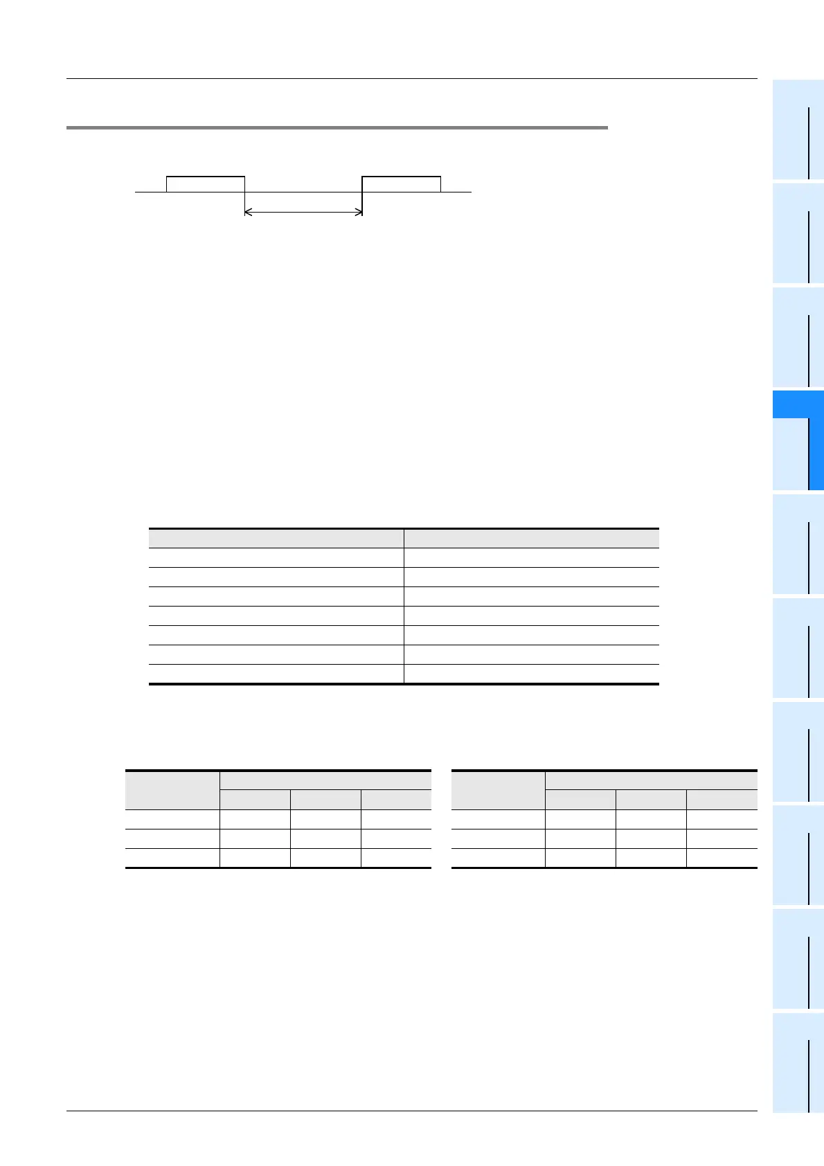
1. Data transfer
2. Data transfer time
Time to read continuous word devices (timers, counters or data registers) in one station = (21
*1
+ 4 × Number
of read points
*2
) × Time to send or receive 1 character (ms) + Interval time + Maximum scan time (special
data register D8012) in PLC × 3 + Message waiting time
Time to write continuous word devices (timers, counters or data registers) in one station = (20
*1
+ 4 × Number
of written points
*2
) × Time to send or receive 1 character (ms) + Interval time + Maximum scan time (special
data register D8012) in PLC + Message waiting time
*1. This is the number of characters when the protocol format 1 is used and the sum check is not
provided.
When the protocol format 4 is used, add "4" to this value.
When the sum check is provided, add "4" to this value also.
*2. The number of points is counted in 1-word units.
3. Time to send or receive one character
The table below shows the time required to send or receive one character when the start bit is 1-bit, the data
length is 7-bit, the parity is 1-bit, and the stop bit is 1-bit.
The tables below show the data transfer times depending on the number of continuously read or written word
devices at the transmission speeds of 9600 bps and 19200 bps when the message waiting time is 0 ms
*1
, the
maximum scan time is 20 ms, and the interval time is 100 ms.
<When the transmission speed is 9600 bps> Unit: sec <When the transmission speed is 19200 bps> Unit: sec
When the types of read or written devices increase, "Data transfer time shown in above table × Number of
device types" is required.
When the number of read or written points exceeds "64"
*2
, the transfer time increase.
Accordingly, for achieving efficient data transfer, it is recommended to decrease the number of types of
transferred devices and use as many continuous device numbers as possible.
*1. The message waiting time is "0" when the RS-485 interface and two-pair wiring are used.
The message waiting time is "0" also when the RS-232C interface is used.
When one-pair wiring is adopted, a message waiting time of 70 to 150 ms is required for each transfer.
Add this message waiting time.
*2. The maximum number of points is 64 for the FX
2(FX), FX2C, FX1N, FX2N, FX3U, FX1NC, FX2NC and
FX
3UC Series. The maximum number of points is as follows for the FX0N and FX1S Series:
Maximum number of read points : 13
Maximum number of written points: 11
Transmission speed (baud rate) (bps) Time to send or receive 1 character (ms)
300 33.34
600 16.67
1200 8.34
2400 4.17
4800 2.08
9600 1.04
19200 0.52
Number of
data points
Number of stations
Number of
data points
Number of stations
1 8 16 1 8 16
10 0.3 1.9 3.7 10 0.2 1.6 3.2
32 0.4 2.6 5.2 32 0.3 2.0 3.9
64 0.5 3.7 7.3 64 0.4 2.5 5.0
Interval time
Data transfer Data transfer

 Loading...


