D-51
FX Series PLC User's Manual - Data Communication Edition
Computer Link
7 Commands
7.2 WR Command [Reads Device Memory in 1-Word Units]
A
Common Items
B
N:N Network
C
Parallel Link
D
Computer Link
E
Inverter
Communication
F
Non-Protocol
Communication
(RS/RS2 Instruction)
G
Non-Protocol
Communication
(FX
2N
-232IF)
H
Programming
Communication
I
Remote
Maintenance
Apx.
Discontinued
models
7.2 WR Command [Reads Device Memory in 1-Word Units]
This section explains the control procedure specification method and specification examples when the word
device memory is read all at once or when the bit device memory is read (in 16-point units) all at once.
1. Specification method
The specification method in the control procedure format 1 is shown below:
1) Specify the device point range while satisfying the following conditions:
-1 ≤ Number of device points ≤ 64
*1
(32
*1
in case of bit devices)
- Head device number + Number of device points ("Number of devices × 16" in case of bit devices) -1 ≤
Maximum device number
- When 32-bit devices (CN200 to CN255) are read, one device point is handled as two word data.
Accordingly, up to 32 device points
*2
can be specified.
2) Express the station number, PLC number, number of device points and sum check code in hexadecimal.
*1. Up to 13 device points in the FX
1S and FX0N Series
*2. Up to 6 device points in the FX
1S and FX0N Series
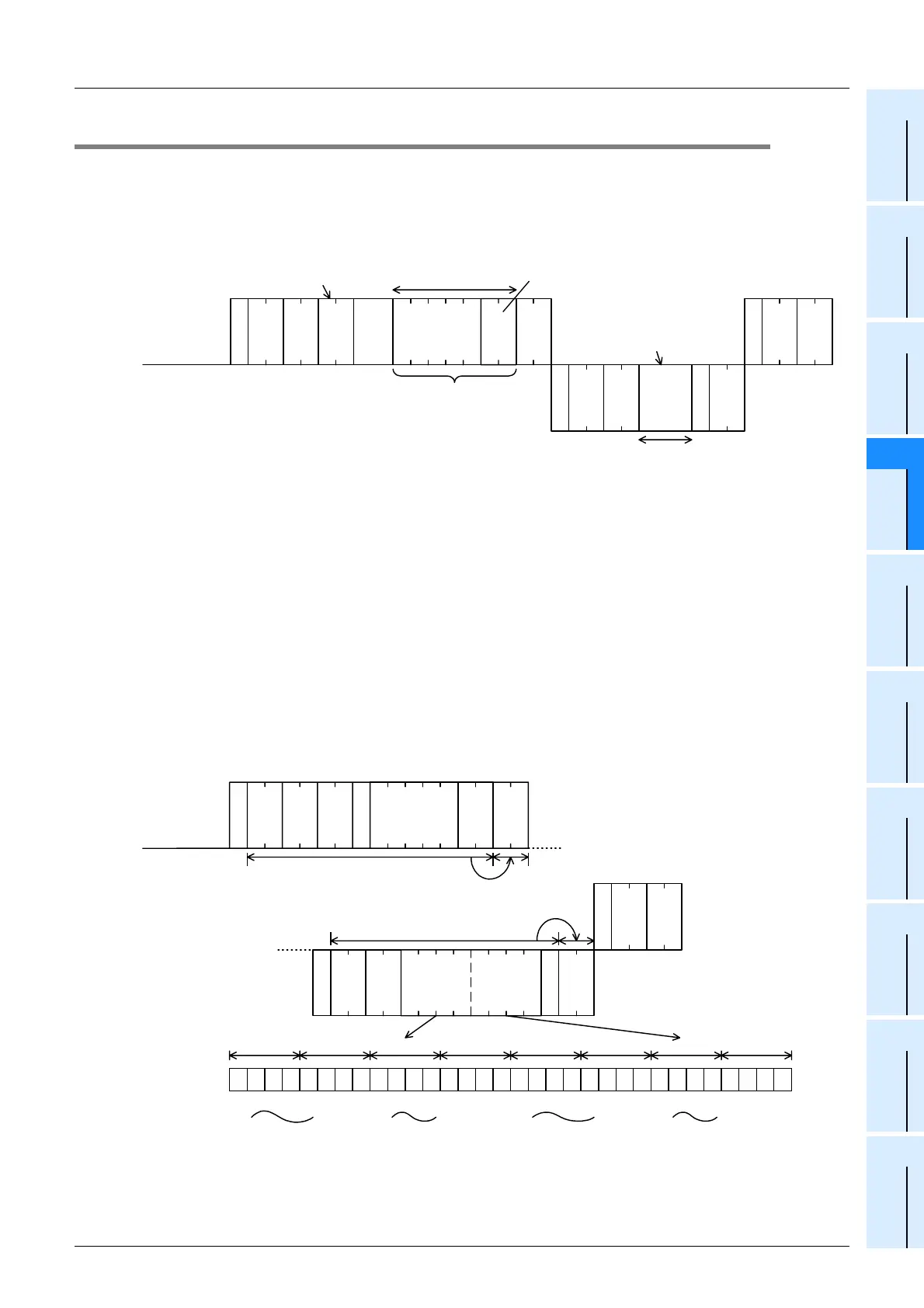
2. Specification examples
Example 1: When reading the contents of thirty-two devices from X040 to X077 in the PLC whose station
number is 5 (while the message waiting time is set to 0 ms)
E
N
Q
PLC No.
WR
S
T
X
*
E
T
X
A
C
K
Character area B
Batch read command (unit: word)
One device uses 4 characters.
Four digits (hexadecimal)
express one word data.
Computer side
PLC side
Head device
(5 characters)
Read device range
specification
Character area A
Number of device points
(2 characters (hexadecimal)
* Data on specified number of device points
(Characters of specified number of device points)
Station
No.
Sum check
code
Station
No.
Sum check
code
Station
No.
PLC No.
PLC No.
Message
wait time
A
C
K
0 5 F F
E
T
X
0 8
S
T
X
0 5 F F 1 2 3 4 A B C D
0 2 4 8
E
N
Q
0 5 F F W R 0
This range is regarded as the
sum check target.
This range is regarded as the
sum check target.
35
H
30
H
46
H
46
H
52
H
57
H
30
H
58
H
30
H
34
H
30
H
30
H
32
H
30
H
38
H
34
H
05
H
35
H
30
H
46
H
46
H
02
H
38
H
30
H
03
H
35
H
30
H
46
H
46
H
06
H
31
H
34
H
33
H
32
H
41
H
44
H
43
H
42
H
0 0 0 0101010001 1111100101010 0 0111 0
X
0
6
0
12 DCBA43
X
0
6
1
X
0
6
2
X
0
6
3
X
0
6
7
X
0
7
0
X
0
7
1
X
0
7
2
X
0
7
7
X
0
4
0
X
0
4
1
X
0
4
2
X
0
4
3
X
0
4
7
X
0
5
0
X
0
5
1
X
0
5
2
X
0
5
7
Computer side
PLC side
X0040

 Loading...


