D-14
FX Series PLC User's Manual - Data Communication Edition
Computer Link
3 System Configuration and Equipment Selection
3.1 System Configuration
3. System Configuration and Equipment Selection
This chapter explains the system configuration and communication equipment selection operating in
accordance with RS-485 or RS-232C required by FX PLCs.
3.1 System Configuration
This section outlines the system configuration required to use computer link.
Connect (optional) equipment operating in accordance with RS-485 or RS-232C to the FX PLC main unit.
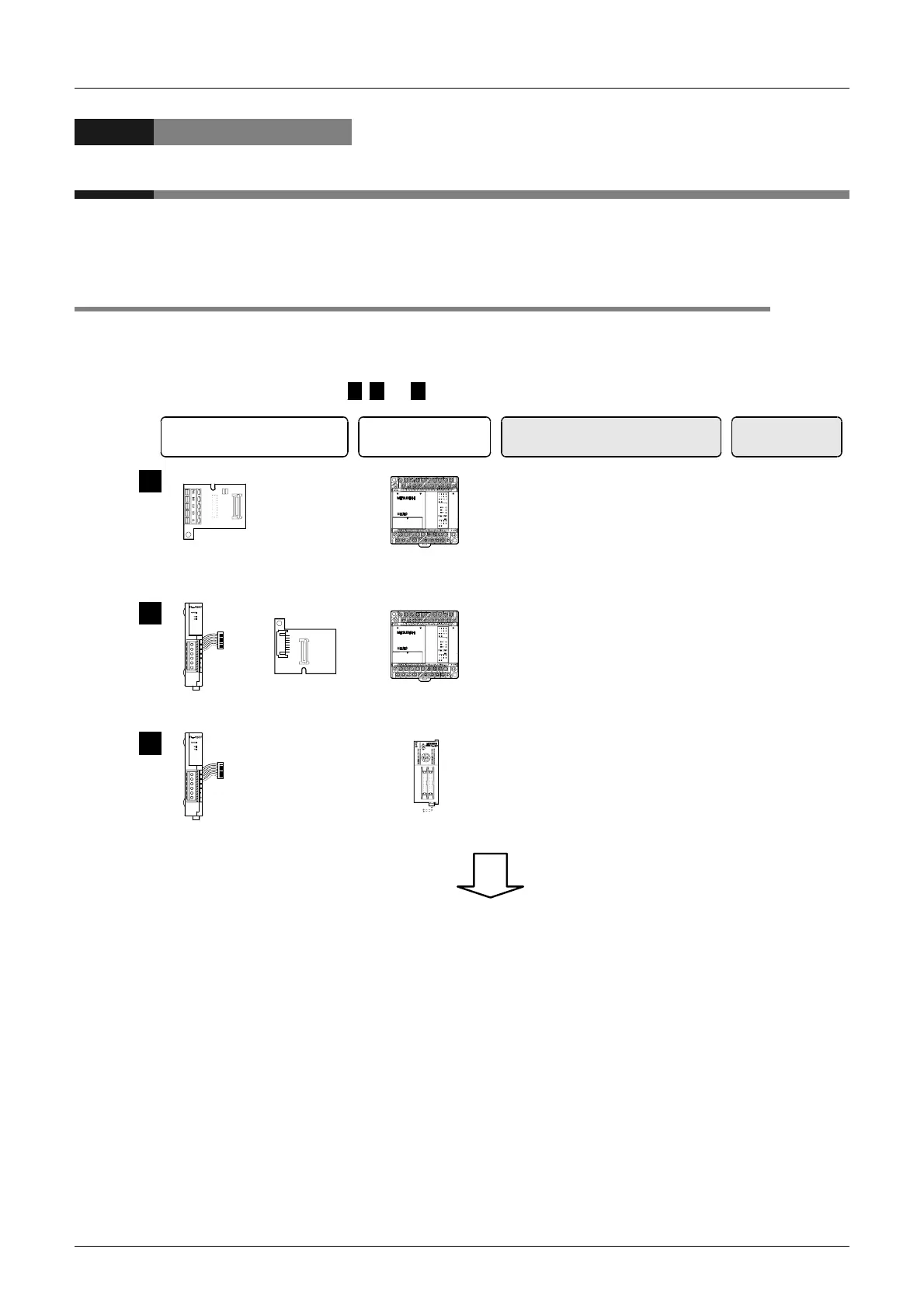
, and indicate the communication equipment combination patterns.
1 2 3
Communication equipment operating
in accordance with RS-485 or
RS-232C
+
FX PLC
+
Communication
board
Communication
adapter
+
Special adapter
connection
board
This is the communication board built
into the PLC, reducing the installation
area.
Important point in selection
Attach the special adapter connection
board to the main unit, and then
attach the communication adapter to
the left side of the main unit.
Total extension
distance
RS-485: 50 m
(164' 0")
RS-232C: 15 m
(49' 2")
RS-485: 500 m
(1640' 5")
RS-232C: 15 m
(49' 2")
1
2
+
Communication
adapter
Attach the communication adapter to
the left side of the main unit.
3
For communication equipment combinations for each FX Series, refer to the next page.
RS-485: 500 m
(1640' 5")
RS-232C: 15 m
(49' 2")

 Loading...


