E-3
FX Series PLC User's Manual - Data Communication Edition
Inverter Communication
1 Outline
1.1 Outline of System
A
Common Items
B
N:N Network
C
Parallel Link
D
Computer Link
E
Inverter
Communication
F
Non-Protocol
Communication
(RS/RS2 Instruction)
G
Non-Protocol
Communication
(FX
2N
-232IF)
H
Programming
Communication
I
Remote
Maintenance
Apx.
Discontinued
models
1. Outline
This chapter explains inverter communication.
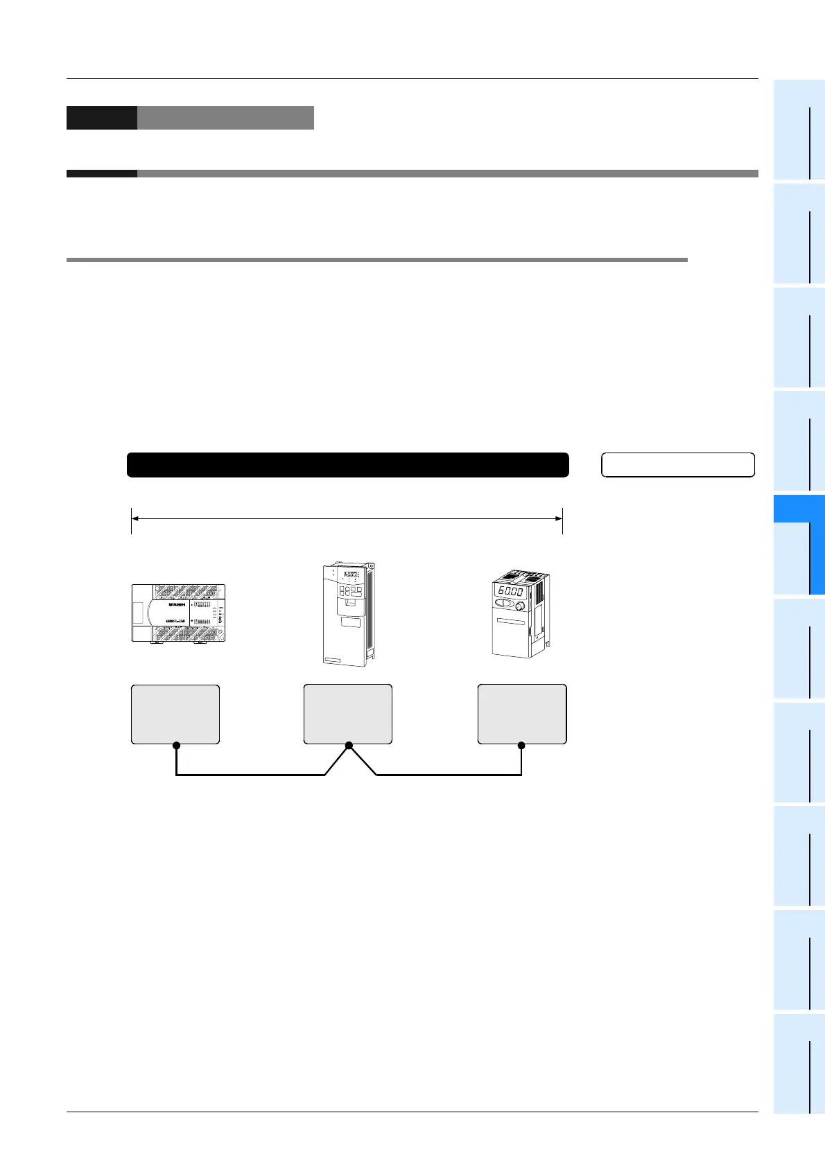
1.1 Outline of System
Inverter communication allows connection between an FX PLC and up to eight inverters to monitor operations
of inverters, give various commands to inverters and read and write inventer parameters through
communication via RS-485 .
1) Mitsubishi general-purpose inverters FREQROL F700, A700, E700,
V500, F500, A500, E500 and S500
(containing the communication type) Series can be linked.
(F700, A700, E700, V500 and F500 Series inverters can be connected only to FX
3U and FX3UC PLCs.)
2) Inverter operations can be monitored, various command can be given to inverters, and parameters can
be read or written in inverters.
3) The total extension distance is 500m (1640' 5") maximum (for the system configured with 485ADP only).
.......
For selection,
refer to Chapter 3.
Communication
equipment
operating in
accordance with
RS-485
Built-in PU port
in accordance
with RS-485
Built-in PU port
in accordance
with RS-485
FX PLC Inverter
Inverter
Master station Station No. 1 Station No. n
500m (1640' 5") [50m (164' 0") when 485BD is included]
.......
Up to eight inverters
Number of linked units
Total extension distance
For the specifications,
refer to Chapter 2.
.......
For wiring,
refer to Chapter 4.
++
.......
To check available PLC
models, refer to Section 1.3.
For the communication
setting of inverters,
refer to Chapter 5.
Important points and reference
chapter/paragraph
System
.......
+
......

 Loading...


