E-26
FX Series PLC User's Manual - Data Communication Edition
Inverter Communication
4 Wiring
4.8 Connection Diagram
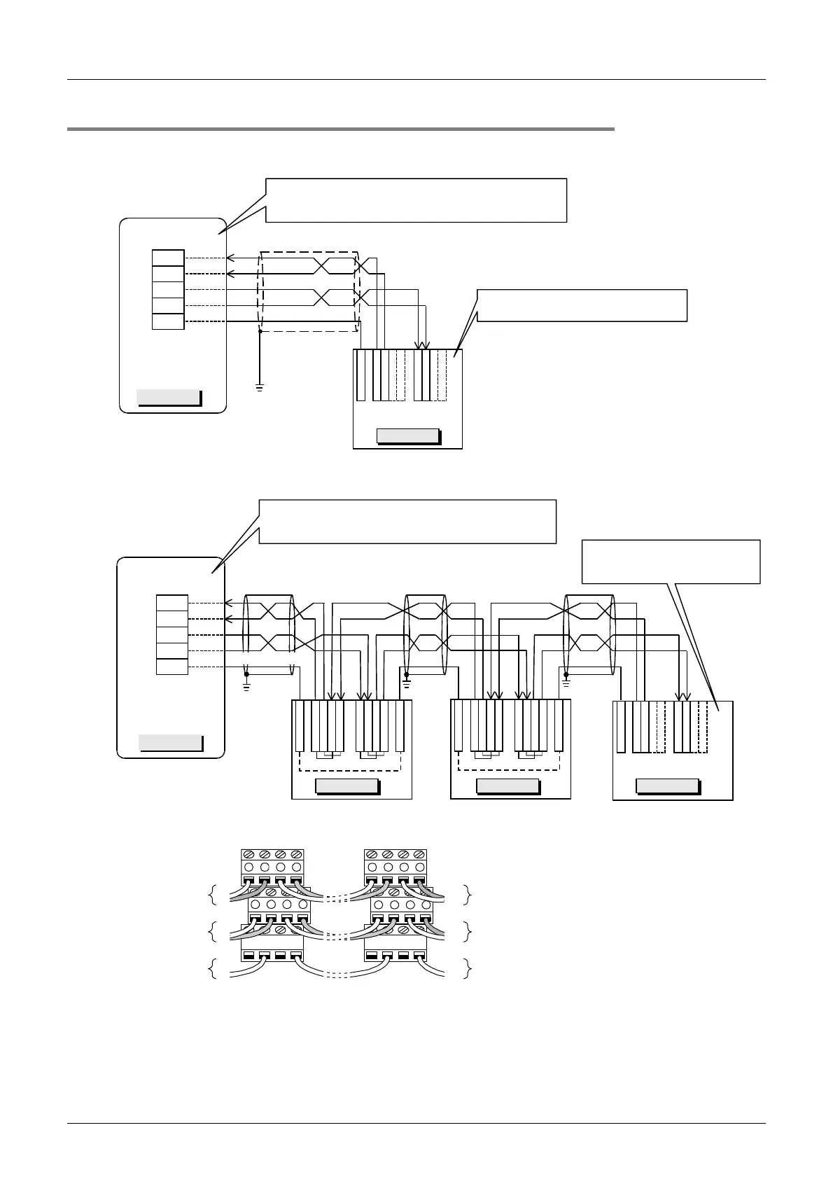
4.8.3 For F700 and A700 Series (built-in RS-485 terminal)
1. When one inverter is connected
2. When two or more (up to eight) inverters are connected
When adopting branches, perform the wiring as shown below:
Set the terminal resistor switch to the
"100
Ω
" side.
Twisted pair cable
(0.3mm
2
or more)
0.3mm
2
or more
R
D
B
1
R
D
A
1
S
D
A
1
S
D
B
1
S
G
Inverter
Terminal resistor: 110
Ω
- FX
3U
-485-BD
- FX
3U
-485ADP(-MB): Set the built-in selector switch.
PLC
RDA
RDB
SDA
SDB
SG
FX
3U
-485-BD
FX
3U
-485ADP(-MB)
Class-D
grounding
RDA
RDB
SDA
SDB
SG
S
D
B
2
S
D
B
1
S
G
R
D
B
2
R
D
B
1
S
G
S
D
A
2
S
D
B
2
S
D
B
1
S
D
A
1
S
G
R
D
A
2
R
D
B
2
R
D
B
1
R
D
A
1
S
G
R
D
A
1
R
D
B
1
S
D
B
1
S
D
A
1
S
G
S
D
A
1
S
D
A
2
R
D
A
1
R
D
A
2
FX
3U
-485-BD
FX
3U
-485ADP(-MB)
Terminal resistor: 110
Ω
- FX
3U
-485-BD
- FX
3U
-485ADP(-MB): Set the built-in selector switch.
. . . .
0.3mm
2
or more
Class-D
grounding
Class-D
grounding
Class-D
grounding
Inverter Inverter Inverter
PLC
Twisted pair cable
(0.3mm
2
or more)
Set the terminal resistor switch
to "100
Ω
" in the inverter located
furthest away from the PLC.
Connect them
to SDA and
SDB in PLC.
Connect them
to RDA and
RDB in PLC.
Connect it to
SG in PLC.
Connect them to
RDA1 and RDB1 in
next inverter.
Connect them to
SDA1 and SDB1 in
next inverter.
Connect it to SG in
next inverter.
VCC
RXDRXD
VCC
TXD TXD
SG SGSG SG
+-+-
+-+- +-+-
+-+-

 Loading...


