D-61
FX Series PLC User's Manual - Data Communication Edition
Computer Link
7 Commands
7.8 WT Command [Tests Device Memory in 1-Word Units (by Writing Arbitrarily)]
A
Common Items
B
N:N Network
C
Parallel Link
D
Computer Link
E
Inverter
Communication
F
Non-Protocol
Communication
(RS/RS2 Instruction)
G
Non-Protocol
Communication
(FX
2N
-232IF)
H
Programming
Communication
I
Remote
Maintenance
Apx.
Discontinued
models
7.8 WT Command [Tests Device Memory in 1-Word Units (by Writing Arbitrarily)]
This section explains the control procedure specification method and shows a specification example when the
word device memory and bit device memory (in 16-point units) are specified arbitrarily and written all at once.
Word devices and bit devices (
in 16-point units
) can be specified together. However, the WT command
cannot handle 32-bit word devices C200 to C255 (CN200 to CN255).
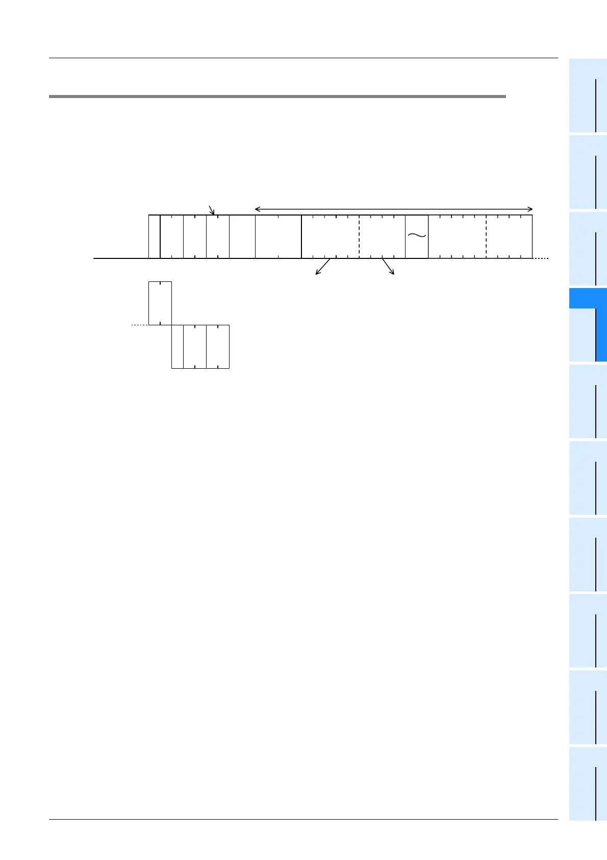
1. Specification method
The specification method in the control procedure format 1 is shown below:
1) Specify the device point range while satisfying the following conditions:
-1 ≤ Number of device points ≤ 10
*1
(in unit of 10
*1
in case of bit devices (One unit indicates 16 points.))
2) Express the station number, PLC number, number of device points and sum check code in hexadecimal.
3) The WT command cannot handle 32-bit word devices C200 to C255 (CN200 to CN255).
*1. 6 in the FX
1S and FX0N Series
E
N
Q
W T
Test (write arbitrarily) command (unit: word)
Number of
device points
(2 characters
(hexadecimal))
Character area A
When specifying bit devices,
specify the head device.
One device uses 4 characters. Four digits
(hexadecimal) express one data word.
Computer side
PLC side
Device
(5 characters)
Data
(4 characters)
Device
(5 characters)
Data
(4 characters)
A
C
K
PLC No.
Station
No.
Message
wait time
Sum check
code
PLC No.
Station
No.

 Loading...


