G-9
FX Series PLC User's Manual - Data Communication Edition
Non-Protocol Communication (FX2N-232IF)
3 System Configuration and Selection
3.1 System Configuration
A
Common Items
B
N:N Network
C
Parallel Link
D
Computer Link
E
Inverter
Communication
F
Non-Protocol
Communication
(RS/RS2 Instruction)
G
Non-Protocol
Communication
(FX
2N
-232IF)
H
Programming
Communication
I
Remote
Maintenance
Apx.
Discontinued
models
3. System Configuration and Selection
This chapter explains the system configuration and selection of the FX PLC and 232IF.
3.1 System Configuration
This section outlines the system configuration required to use the 232IF.
3.2 Applicable FX PLC and Communication Equipment
Select a 232IF combination, and put a check mark in the "Check" column.
During selection, pay attention to the following:
• The capacity of the 5V DC power supplied from the PLC is limited. The current consumption at 5V DC of
the 232IF is 40 mA. Make sure that total current consumption at 5V DC including other blocks does not
exceed the specified value.
FX Series Communication equipment (option)
Total extension
distance
Check
FX
2N
15 m
(49' 2")
FX
2NC
15 m
(49' 2")
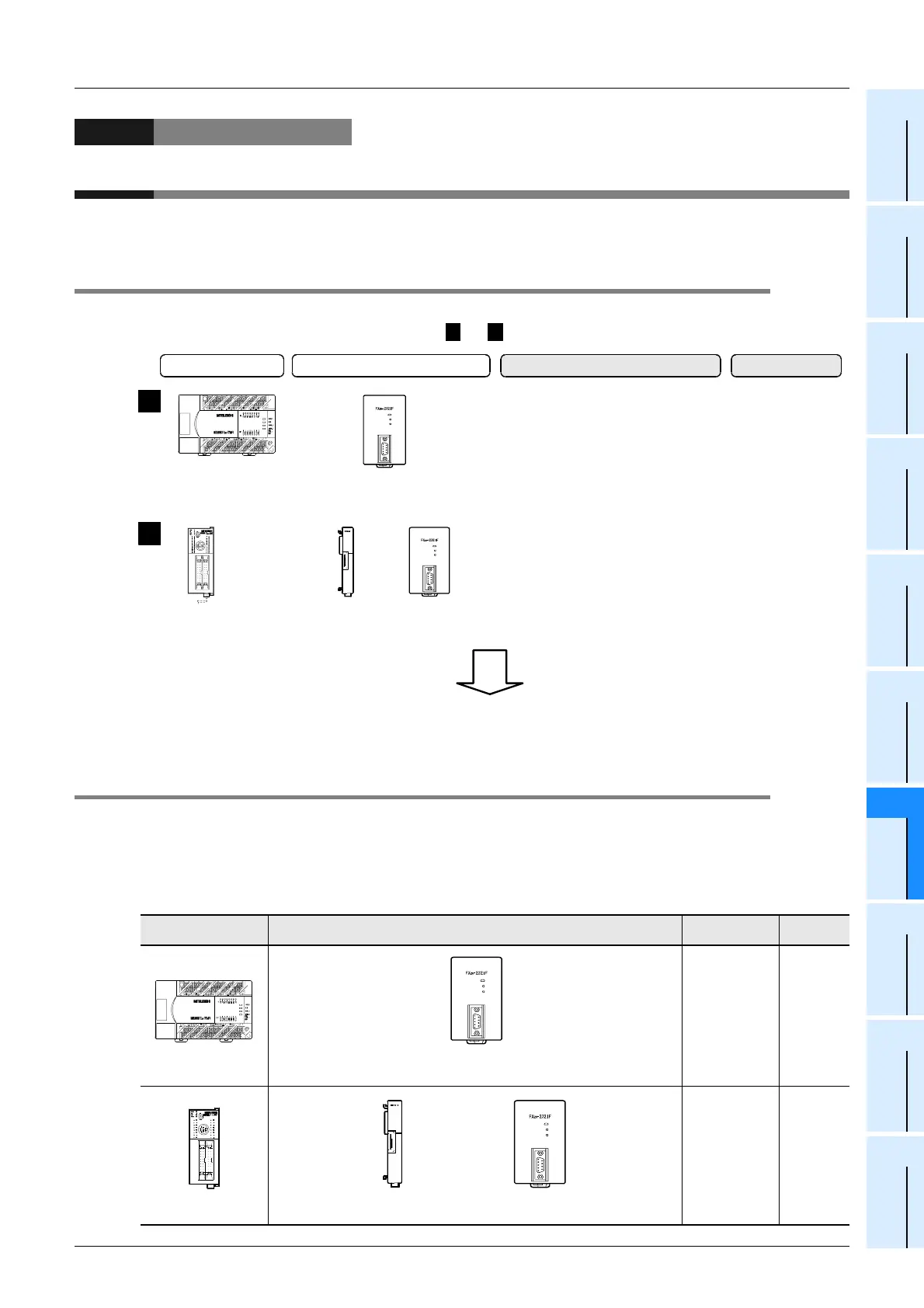
and indicate the communication equipment combination patterns.
1 2
FX PLC FX
2N
-232IF
FX
2N
Series
FX
3U
Series
FX
2NC
Series
FX
3UC
Series
Connector
conversion
interface
Attach the 232IF to the right side of
the main unit.
Important point in selection
Attach the connector conversion
interface to the right side of the main
unit, and then attach the 232IF to the
right side of the connector conversion
interface.
Total extension
distance
15 m
(49' 2")
15 m
(49' 2")
1
2
For communication equipment combinations for each FX Series, refer to the next section.
+
++
POWER
SD
RD
POWER
SD
RD
FX
2N
-232IF
(9-pin D-Sub, male)
POWER
SD
RD
1
FX
2N
-232IF
9-
in D-Sub, male
FX
2NC
-CNV-IF
+
POWER
SD
RD

 Loading...


