E-74
FX Series PLC User's Manual - Data Communication Edition
Inverter Communication
9 Creating Programs (for FX3U and FX3UC PLCs)
9.3 Common Items in Inverter Communication Instructions
9.3 Common Items in Inverter Communication Instructions
9.3.1 Inverter communication types (IVCK to IVBWR)
Execute inventer communication using the following applied instructions.
There are five types of applied instructions, "IVCK (FNC270) to IVBWR (FNC274)", depending on the data
communication direction and parameter reading/writing direction.
9.3.2 Function and operation
1. Communication start timing
At the rising edge (OFF→ON) of the drive condition, the PLC starts communication with an inverter.
Even if the drive condition turns OFF during communication with an inverter, the PLC executes
communication until the last instruction.
When the drive condition is always ON, the PLC executes communication repeatedly.
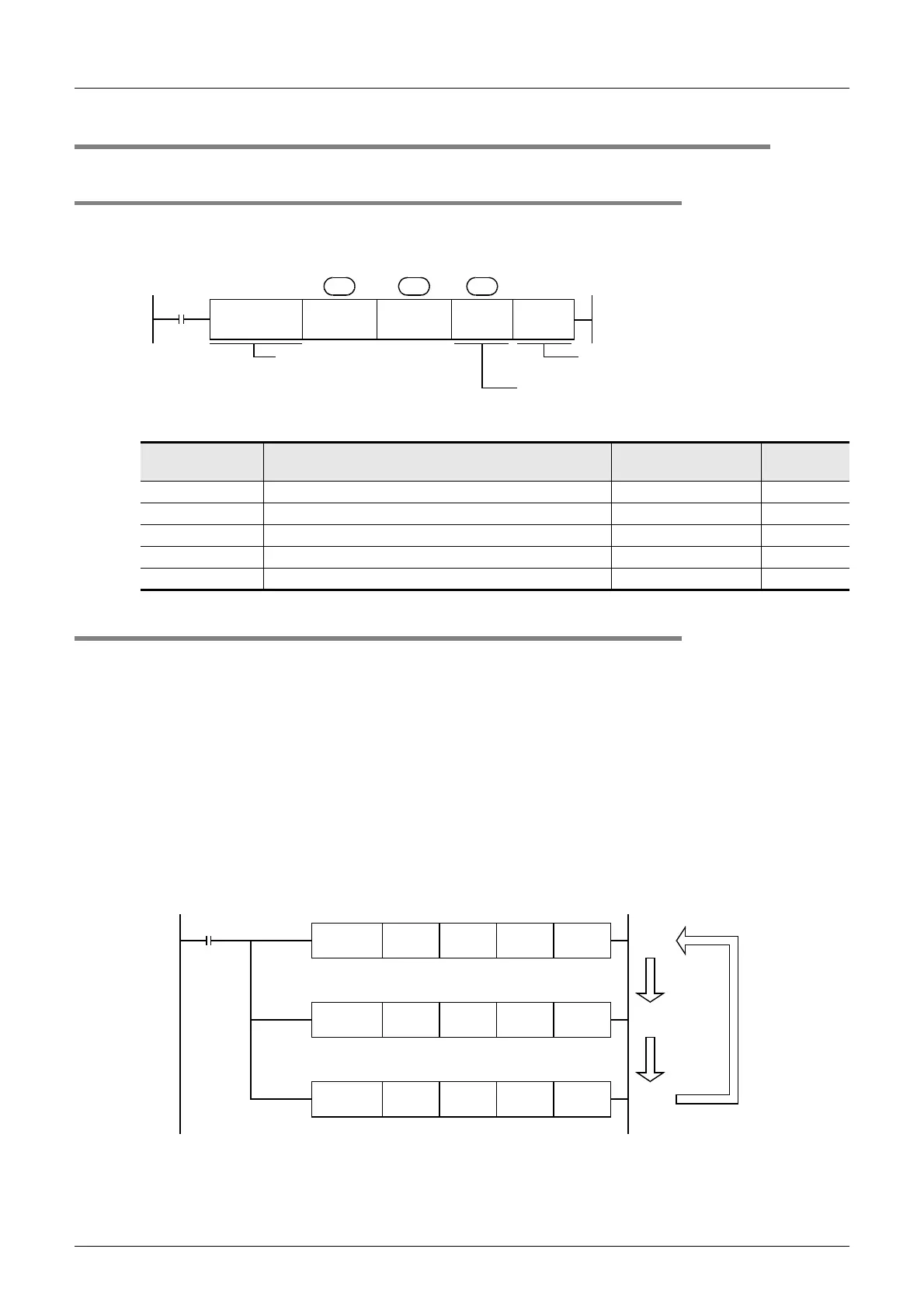
2. Simultaneous driving of instructions and communication processing
1) Driving instructions at the same time
- Two or more IVCK (FNC270) to IVBWR (FNC274) instructions can be programmed, and driven at the
same time.
- When two or more instructions are driven at the same time in the channel used for communication, the
latter inverter communication instruction in the program is executed after the current communication
with the inverter has finished.
Instruction Function Control direction
Detailed
explanation
IVCK(FNC270) Monitors operations of an inverter. PLC ← inverter 9.4
IVDR(FNC271) Controls operations of an inverter. PLC → inverter 9.5
IVRD(FNC272) Reads a parameter from an inverter. PLC ← inverter 9.6
IVWR(FNC273) Writes a parameter to an inverter. PLC → inverter 9.7
IVBWR(FNC274) Writes parameters to an inverter all at once. PLC → inverter 9.8
Inverter
communication
instruction
Inverter
station
number
Inverter
instruction
code
Read/
Write
S
1
S
2
S
3
Only 16-bit type is applicable.
DIVCK (32-bit type), IVCKP
(pulse operation type) and
DIVCKP (32-bit pulse operation
type) are not applicable.
Read value storage destination
or value written to inverter
Used
channel
n
K1:ch1
K2:ch2
M8000
FNC273
IVWR
FNC271
IVDR
FNC270
IVCK
RUN
monitor
(1)
(2)
(3)
M8151
ON
→
OFF
M8151
ON
→
OFF

 Loading...


