G-25
FX Series PLC User's Manual - Data Communication Edition
Non-Protocol Communication (FX2N-232IF)
5 Creating Programs
5.4 Buffer Memory (BFM)
A
Common Items
B
N:N Network
C
Parallel Link
D
Computer Link
E
Inverter
Communication
F
Non-Protocol
Communication
(RS/RS2 Instruction)
G
Non-Protocol
Communication
(FX
2N
-232IF)
H
Programming
Communication
I
Remote
Maintenance
Apx.
Discontinued
models
5.4.4 Maximum number of receivable bytes <BFM #2>
Setting range: 1 to 512 bytes (when the buffer data length is 16-bit)
1 to 256 bytes (when the buffer data length is 8-bit)
"0" is handled as "512" or "256 bytes". The initial value is "0".
This bit specifies the maximum number of bytes which can be received by the 232IF.
When the 232IF receives the maximum number of receivable bytes, it sets the receiving complete flag (BFM
#28, b1) to ON.
If the receiving terminator (BFM #11 and 10) or receiving timeout time (BFM #3) are set, the 232IF recognizes
that receiving is completed even if the already received data does not reach the maximum number of
receivable bytes when either condition is satisfied.
5.4.5 Receiving timeout time <BFM #3>
Setting range: 1 to 32767 (× 10 ms)
"0" is regarded as no timeout time. The initial value is "0".
This bit specifies the waiting time limit for receive data.
When the 232IF does not receive the next set of data within the receiving timeout time after the receiving
edge of each data, the receiving timeout flag (BFM #28, b2) turns ON. At this time, the 232IF recognizes that
receiving is completed, and sets the receiving complete flag (BFM #28, b1) to ON.
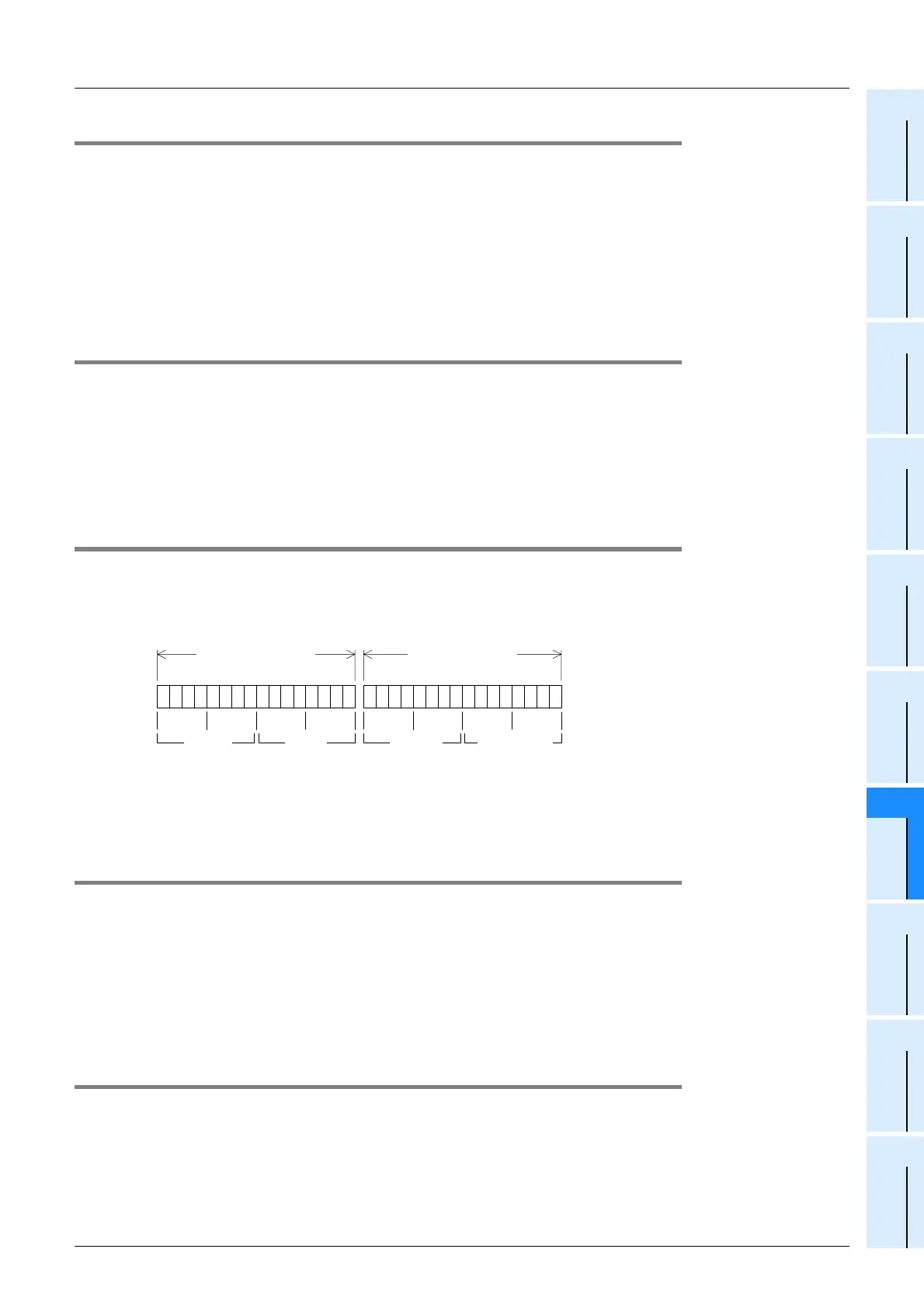
5.4.6 Sending header <BFM #5 (highest-order 2 bytes) and BFM #4 (lowest-order 2
bytes)>
Setting range: 4 bytes maximum, 0 suppression
The initial value is "0" (no sending header).
Up to four headers can be specified for the 232IF send data. When the number of headers is less than 4, "0"s
in upper positions are ignored (0 suppression) and are not transferred.
The transfer order is "fourth header
→ third header → second header → first header" when four headers are
set.
5.4.7 Sending terminator <BFM #7 (highest-order 2 bytes) and BFM #6 (lowest-order 2
bytes)
Setting range: 4 bytes maximum, 0 suppression
The initial value is "0" (no sending terminator).
Up to four terminators can be specified for the 232IF send data. When the number of terminators is less than
4, "0"s in upper positions are ignored (0 suppression) and are not transferred.
For the terminator transferred first, specify ASCII code from "01
H" to "1FH". (For other terminators after that,
any ASCII code other than "01
H" to "1FH" can be specified.)
The register structure and transfer order are the same as those of the sending header described above.
5.4.8 Receiving header <BFM #9 (highest-order 2 bytes) and BFM #8 (lowest-order 2
bytes)>
Setting range: 4 bytes maximum, 0 suppression
The initial value is "0" (no sending header).
Up to four headers can be specified for the 232IF received data. When the number of headers is less than 4,
"0"s in upper positions are ignored (0 suppression) and are not transferred.
The register structure and transfer order are the same as those of the sending header described above.
b15
0
0 0 0 0 0 0 0 0 0 0 0 0 0 0 0 0
b0
0
0 0
BFM #5
(highest-order 2 bytes)
Fourth
header
Third
header
b15
0
0 0 0 0 0 0 0 0 0 0 0 0 0 0 1 0
b0
0
0 2
BFM #4
(lowest-order 2 bytes)
Second
header
First header
Example:
02H (STX)

 Loading...


