I-18
FX Series PLC User's Manual - Data Communication Edition
Remote Maintenance
4 Wiring
4.1 Wiring Procedure
4. Wiring
This chapter explains the wiring.
4.1 Wiring Procedure
1 Turning OFF the PLC power
Before starting any wiring work, make sure that the PLC power is OFF.
2 Checking the connector shape
When a cable is included with the modem, check the shape of the RS-232C connector in the
personal computer to be connected, the shape of the connector in the communication equipment
operating in accordance with RS-232C for the PLC, and male or female type.
3 Connecting the RS-232C ports in the modem and the PLC with a cable
Check the shape of the connector (number of pins) in the communication equipment operating in
accordance with RS-232C to be connected to the PLC. Each cable has either connector shape:
- 9-pin D-Sub, female
- 25-pin D-Sub, male
4
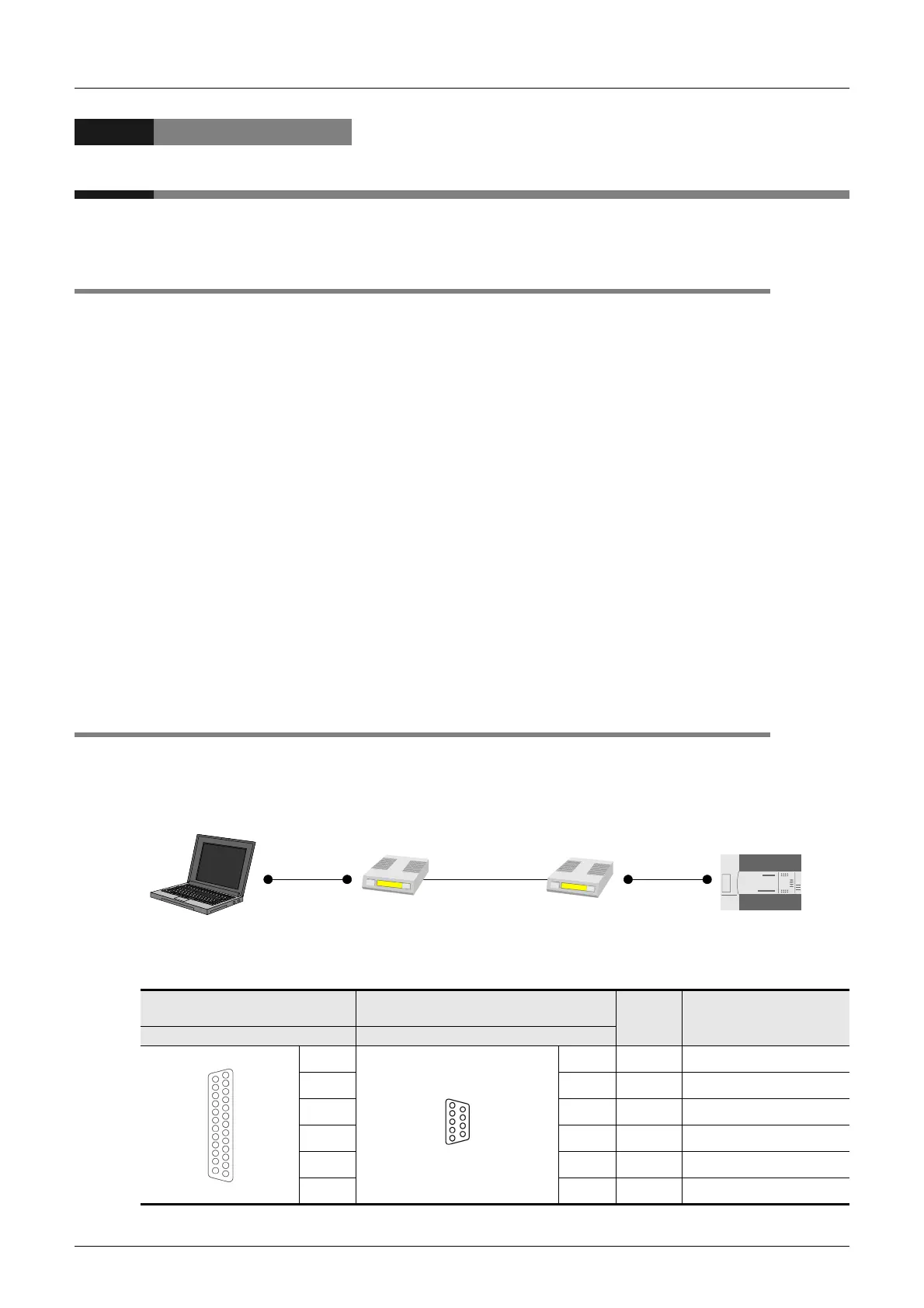
Connecting the personal computer and the modem with a cable for remote access
Check the shape of the RS-232C connector (number of pins) on the personal computer for remote access.
4.2 Connection Diagram
1. To connect the modem, use a cable included with the modem or cable described in the
modem manual.
2. The table below shows the pin arrangement in the communication equipment operating in
accordance with RS-232C for the FX PLC.
*1. The FX2NC-232ADP does not use the CD signal.
FX0N-232ADP
FX
1N
-232-BD, FX
2N
-232-BD, FX
2NC
-232ADP,
FX
3U
-232-BD, FX
3U
-232ADP(-MB)
Signal
name
Function
25-pin D-Sub, female 9-pin D-Sub, male
—
1
*1
CD
Receiving carrier detection
32
RD (RXD)
Receive data input
23
SD (TXD)
Send data output
20 4
ER (DTR)
Data terminal ready
75
SG (GND)
Signal ground
66
DR (DSR)
Data set ready
Remote access
Personal computer
Cable
Modem
Modem
Line
general telephone
line, etc.
Cable
PLC
25
13
1
14
5
1
9
6

 Loading...


