F-50
FX Series PLC User's Manual - Data Communication Edition
Non-Protocol Communication (RS/RS2 Instruction)
8 Creating Programs (RS2 Instruction)
8.2 How to Use RS2 Instruction
8.2.1 Applicable frames
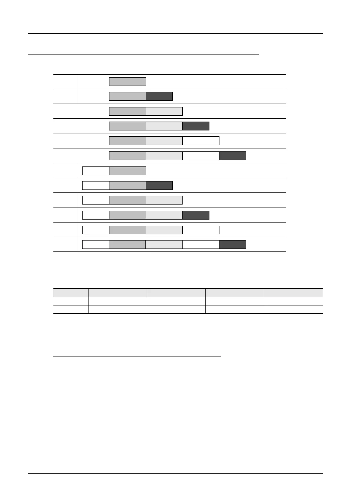
Message frames used in communication can be selected by setting the communication format.
The table below shows message frames applicable to the RS2 instruction.
1. Header
When "header provided" is selected in the communication format settings, the values of D8410 and D8411
are used for ch.1, and the values of D8430 and D8431 are used for ch.2.
Up to four headers can be set.
When data is sent, the data set in the devices above is added at the head of the specified send data.
When data is received, receiving begins when the data set in the devices above is received continuously.
Even if "header provided" is selected, headers are not provided if header 1 is set to "00H".
The area before 00H (in 1-byte units) is used to set the headers.
Cautions
Set the header before driving the RS2 instruction. Do not change the setting while the RS2 instruction is
being driven.
1
2
3
4
5
6
7
8
9
10
11
12
Header Header 1 Header 2 Header 3 Header 4
ch1
D8410 (lowest-order byte) D8410 (highest-order byte) D8411 (lowest-order byte) D8411 (highest-order byte)
ch2
D8430 (lowest-order byte) D8430 (highest-order byte D8431 (lowest-order byte) D8431 (highest-order byte)
Data
Data CR+LF
Data Terminator
Data CR+LFTerminator
Data Terminator Sum check
Data Terminator Sum check CR+LF
DataHeader
DataHeader CR+LF
Data TerminatorHeader
DataHeader Terminator CR+LF
DataHeader Terminator Sum check
Header Data Terminator Sum check CR+LF

 Loading...


