E-24
FX Series PLC User's Manual - Data Communication Edition
Inverter Communication
4 Wiring
4.8 Connection Diagram
4.8 Connection Diagram
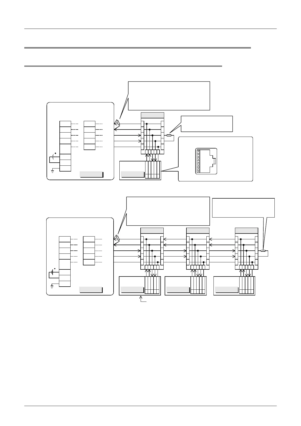
4.8.1 For S500, E500, A500 and E700 Series (PU connector)
1. When one inverter is connected
2. When two or more (up to eight) inverters are connected
24V
DC
50mA
Terminal resistor: 110
Ω
• FX
3U
-485-BD and FX
3U
-485ADP(-MB):
Set the built-in selector switch.
• FX
2N
-485-BD and FX
2NC
-485ADP:
Connect a terminal resistor (supplied)
between the RDA and RDB terminals.
PLC
Distributor
RDA
RDB
SDA
SDB
LINK
SG
24+
24G
RDA
RDB
SDA
SDB
SG
FX
0N
-485ADP
FX
2NC
-485ADP
54361
Connect a terminal
resistor of 100
Ω
, 1/2 W
(not supplied).
10BASE-T
cable
FG
Class-D grounding
Inverter
R
D
B
R
D
A
S
D
A
S
D
B
S
G
PU (RS-485)
connector
54361
5
4
3
6
1
5
4
3
6
1
8
1
Modular jack
When seen from inverter front
(receptacle side)
FX
2N
-485-BD
FX
3U
-485-BD
FX
3U
-485ADP(-MB)
PLC
RDA
RDB
SDA
SDB
LINK
SG
24+
24G
RDA
RDB
SDA
SDB
SG
FX
0N
-485ADP
FX
2N
-485-BD
24V
DC
50mA
FG
Class-D grounding
Distributor
54361
10BASE-T
cable
Inverter
R
D
B
R
D
A
S
D
A
S
D
B
S
G
PU (RS-485)
connector
54361
5
4
3
6
1
5
4
3
6
1
Inverter
R
D
B
R
D
A
S
D
A
S
D
B
S
G
PU (RS-485)
connector
543 6 1
Distributor
543 6 1
5
4
3
6
1
5
4
3
6
1
Inverter
R
D
B
R
D
A
S
D
A
S
D
B
S
G
PU (RS-485)
connector
54361
Distributor
54361
5
4
3
6
1
5
4
3
6
1
...
For the pin arrangement in the connector,
refer to the connection diagram above for one inverter.
FX
2NC
-485ADP
FX
3U
-485-BD
Terminal resistor: 110
Ω
• FX
3U
-485-BD and FX
3U
-485ADP(-MB):
Set the built-in selector switch.
• FX
2N
-485-BD and FX
2NC
-485ADP:
Connect a terminal resistor (supplied)
between the RDA and RDB terminals.
FX
3U
-485ADP(-MB)
Connect a terminal resistor of
100
Ω
, 1/2 W (not supplied) to
the most distant inverter.

 Loading...


