G-12
FX Series PLC User's Manual - Data Communication Edition
Non-Protocol Communication (FX2N-232IF)
4 Wiring
4.1 Pin Arrangement
4. Wiring
This chapter explains the wiring.
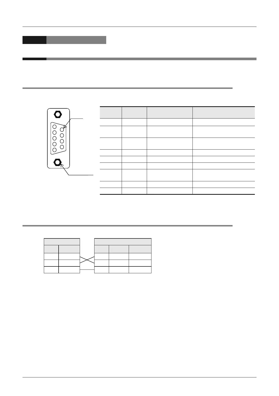
4.1 Pin Arrangement
The table below shows the pin arrangement of the 232IF.
Example of applicable connector: 17JE-13090-02 (D8C2) by DDK Ltd.
*1.The signal inside ( ) is adopted in the interlink connection mode.
4.2 Connection to External Equipment with Terminal Specifications
(without Control Line)
BFM # 0 (communication format): b9 = 0, b8 = 0 (control line not provided)
Pin No.
Signal
name
Function
Signal direction 232IF:
External equipment
1 CD(DCD) Carrier detection
φ
←
φ
2 RD(RXD)
Receive data
(with LED indicator)
←
3 SD(TXD)
Send data
(with LED indicator)
→
4 ER(DTR) Data terminal ready →
5 SG(GND) Signal ground —
6 DR(DSR) Data set ready ←
7 RS(RTS)
Sending request
(receiving enable)
*1
→
8 CS(CTS) Sending enable ←
9 CI(RI) Calling indicator ←
1
2
3
4
5
9
8
7
6
Pin
#4-40UNC
inch screw
PLC side
RS-232C external equipment side
Name FX
2N
-232IF Name
9-pin D-Sub 25-pin D-Sub
SD(TXD)
3
SD(TXD)
32
RD(RXD)
2
RD(RXD)
23
SG(GND)
5
SG(GND)
57

 Loading...


