E-94
FX Series PLC User's Manual - Data Communication Edition
Inverter Communication
10 Practical Program Examples (for FX3U and FX3UC PLCs)
10.2 Practical Example 2
10.2.3 Program example
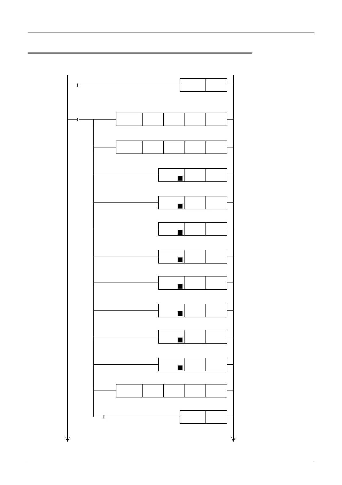
1. Writing parameters to an inverter while the PLC is in RUN mode
*1. When using an E500 Series inverter, use "H2" to specify computer link operation.
M8002
FNC271
IVDR
K0 H0FD H9696 K1
FNC271
IVDR
K0 H0FB H0
*1
K1
Initial pulse
SET M10
FNC 12
MOV
K1 D200
P
FNC 12
MOV
K12000 D201
P
FNC 12
MOV
K2 D202
P
FNC 12
MOV
K500 D203
P
FNC 12
MOV
K7 D204
P
FNC 12
MOV
K10 D205
P
FNC 12
MOV
K8 D206
P
FNC 12
MOV
K10 D207
P
FNC274
IVBWR
K0 K4 D200 K1
The write
instruction
is driven
Driving of
write
instruction
M10
M8029
RST M10
The inverter is reset
Computer link operation
is specified
The maximum
frequency (Pr. 1) is
specified
The maximum
frequency (Pr. 1) is
set to "120 Hz"
The minimum
frequency (Pr. 2) is
specified
The minimum
frequency (Pr. 2) is
set to "5 Hz"
The acceleration time
(Pr. 7) is specified
The acceleration time
(Pr. 7) is set to "1 sec"
The deceleration time
(Pr. 8) is specified
The deceleration time
(Pr. 8) is set to "1 sec"
The parameters are written
all at once
D200 to D207
(Pr. 1, Pr. 2, Pr. 7 and Pr. 8)
Driving of
write
instruction
Instruction execute
complete

 Loading...


