D-29
FX Series PLC User's Manual - Data Communication Edition
Computer Link
4 Wiring
4.4 Connection Diagram for RS-232C
A
Common Items
B
N:N Network
C
Parallel Link
D
Computer Link
E
Inverter
Communication
F
Non-Protocol
Communication
(RS/RS2 Instruction)
G
Non-Protocol
Communication
(FX
2N
-232IF)
H
Programming
Communication
I
Remote
Maintenance
Apx.
Discontinued
models
4.4 Connection Diagram for RS-232C
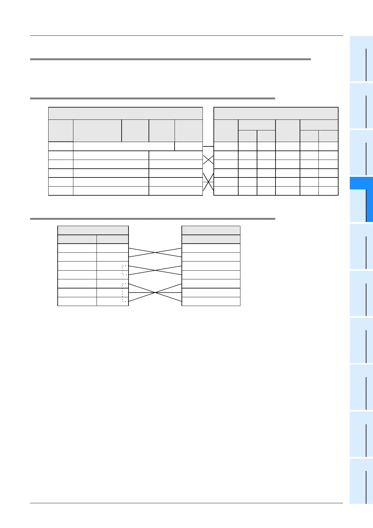
Representative wiring examples are shown in this section. When pin numbers in the external equipment are
different, wire the pins as shown below.
4.4.1 Connection diagram between FX PLC and personal computer
4.4.2 Connection diagram between FX-485PC-IF and personal computer
External equipment operating in accordance
with RS-232C
Name
When CS and
RS are used
Name
When DR and
ER are used
9-pin
D-Sub
25-pin
D-Sub
9-pin
D-Sub
25-pin
D-Sub
FG
−
1FG
−
1
RD(RXD) 2 3 RD(RXD) 2 3
SD(TXD) 3 2 SD(TXD) 3 2
RS(RTS) 7 4 ER(DTR) 4 20
SG(GND) 5 7 SG(GND) 5 7
CS(CTS) 8 5 DR(DSR) 6 6
FG
RD(RXD)
PLC side
SD(TXD)
ER(DTR)
SG(GND)
DR(DSR)
Name
FX
2N
-232-BD
FX
1N
-232-BD
FX
0N
-
232ADP
FX-232ADP
−
1
23
32
420
57
66
FX
2NC
-
232ADP
FX
3U
-232-BD
FX
3U
-232ADP(-MB)
SD (TXD)
RD (RXD)
RS (RTS)
CS (CTS)
DR (DSR)
SG (GND)
ER (DTR)
Signal name Pin No.
2
3
4
5
6
7
20
485PC-IF
SD (TXD)
RD (RXD)
RS (RTS)
CS (CTS)
DR (DSR)
SG (GND)
ER (DTR)
Signal name
Personal computer

 Loading...


