D-66
FX Series PLC User's Manual - Data Communication Edition
Computer Link
7 Commands
7.11 PC Command [Reads PLC Model Name]
7.11 PC Command [Reads PLC Model Name]
This section explains the control procedure specification method and specification example when the model
name of a PLC linked to the computer is read.
7.11.1 PLC model name (CPU) and read contents
7.11.2 Control procedure specification method and specification example
1. Specification method
The specification method for control procedure format 1 is shown below:
Express the station number, PLC number, number of device points and sum check code in hexadecimal
respectively.
2. Specification example
When reading the model name of the PLC whose station number is 15 (while the message waiting time is set
to 0 ms)
PLC model name (CPU)
Model name code
(hexadecimal)
PLC model name (CPU)
Model name code
(hexadecimal)
FX
1S F2H A2USCPU 82H
FX
0N 8EH A2CPU-S1, A2USCPU-S1 83H
FX
2(FX), FX2C 8DH A3CPU, A3NCPU A3H
FX
1N, FX1NC 9EH A3ACPU 94H
FX
2N, FX2NC 9DH A3HCPU, A3MCPU A4H
FX
3U, FX3UC F3H A3UCPU 84H
A0J2HCPU 98H A4UCPU 85H
A1CPU, A1NCPU A1H A52GCPU 9AH
A1SCPU, A1SJCPU 98H A73CPU A3H
A2CPU(-S1), A2NCPU(-S1), A2SCPU
A2H A7LMS-F A3H
A2ACPU 92H AJ72P25/R25 ABH
A2ACPU-S1 93H AJ72LP25/BR15 8BH
A2CCPU 9AH
E
N
Q
P C
S
T
X
PLC model
name
(2 characters)
E
T
X
A
C
K
Character area B
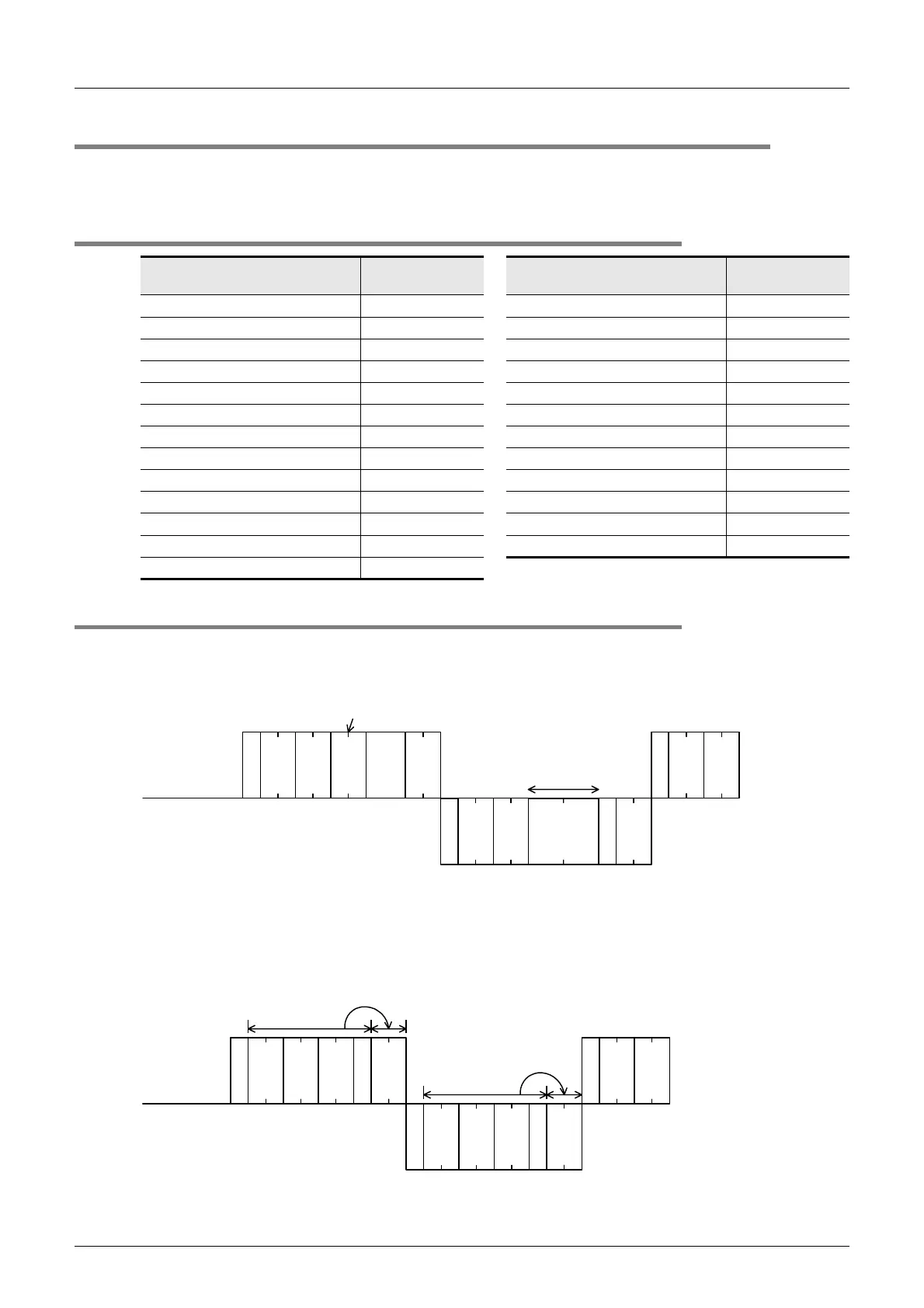
PC command to read the PLC model name
Computer side
PLC side
PLC No.
Station
No.
Message
wait time
Sum check
code
Sum check
code
PLC No.
Station
No.
PLC No.
Station
No.
A
C
K
0 F F F
S
T
X
0 F F F
E
T
X
8 18 D
E
N
Q
0 F F F P C 0 C 5
46
H
30
H
46
H
46
H
43
H
50
H
30
H
35
H
43
H
05
H
46
H
30
H
46
H
46
H
02
H
31
H
38
H
03
H
46
H
30
H
46
H
46
H
06
H
The example above indicates that the model name of the target PLC is the FX
2
(FX) or FX
2C
Series.
44
H
38
H
Computer side
PLC side
This range is regarded as
the sum check target.
This range is regarded as
the sum check target.

 Loading...


