A-5
FX Series PLC User's Manual - Data Communication Edition
Common Items
1 Introduction
1.2 Outline and Features of Communication Types
A
Common Items
B
N:N Network
C
Parallel Link
D
Computer Link
E
Inverter
Communication
F
Non-Protocol
Communication
(RS/RS2 Instruction)
G
Non-Protocol
Communication
(FX
2N
-232IF)
H
Programming
Communication
I
Remote
Maintenance
Apx.
Discontinued
models
1.2.3 Parallel Link
→ Refer to the "Parallel Link" section.
1. Outline
2. Applicable PLCs
: Applicable (If applicable versions are limited, they are described inside ( ).)
—: Not applicable
3. Communication targets
Between FX2(FX), FX2C, FX1S, FX0N, FX1N, FX2N, FX3U, FX1NC, FX2NC, and FX
3UC
Series PLCs
4. Function
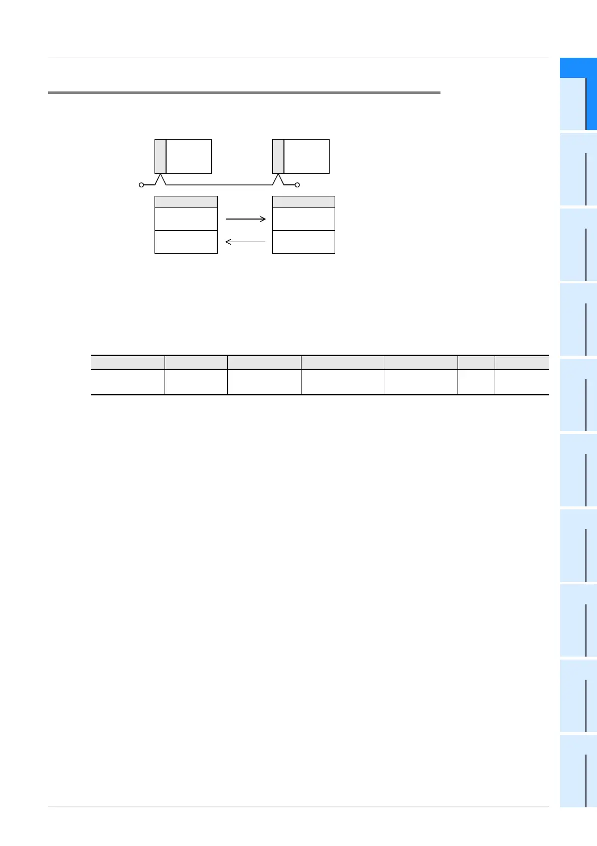
This network automatically transfers data for 100 bit devices (M) and 10 data registers (D) between two PLCs
of the same series.
Between PLCs in the FX
0N or FX1S Series, data can be transferred for 50 bit devices (M) and 10 data
registers (D).
5. Applications
Information can be transferred between two FX PLCs.
(It is recommended to use the N:N Network when connecting two PLCs of the same series among the FX1S,
FX
1N, FX2N, FX3U, FX1NC, FX2NC, and FX3UC Series. N:N Network functionality supports linking of up to eight
FX PLC units, therefore it offers excellent future expandability options.)
PLC FX2(FX),FX2C FX0N FX1S,FX1N,FX1NC FX2N FX2NC FX3U,FX3UC
Communication
applicability
(Ver.1.20 or later)
(Ver.1.04 or later)
RS-485
FX CPU
Master
station
RS-485
FX CPU
Slave
station
100 bit devices (M) and 10 word devices (D)
•
Number of connectable FX PLCs: 2
•
Total extension distance: 500 m (1640' 5") [50 m (164' 0") when 485BD is connected]
*1
*1 The distance is different for the FX
2
-40AW/AP.
Master station
M800 to M899
D490 to D499
M900 to M999
D500 to D509
Slave station
M800 to M899
D490 to D499
M900 to M999
D500 to D509
Terminal
resistor
Terminal
resistor

 Loading...


