C-25
FX Series PLC User's Manual - Data Communication Edition
Parallel Link
4 Wiring
4.2 Selecting Cables and Terminal Resistors
A
Common Items
B
N:N Network
C
Parallel Link
D
Computer Link
E
Inverter
Communication
F
Non-Protocol
Communication
(RS/RS2 Instruction)
G
Non-Protocol
Communication
(FX
2N
-232IF)
H
Programming
Communication
I
Remote
Maintenance
Apx.
Discontinued
models
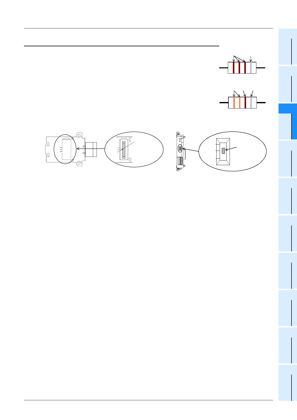
4.2.4 Connecting terminal resistors
In the case of one-pair wiring, connect a terminal resistor to the RDA-RDB signal
terminal of the communication equipment.
In the case of two-pair wiring, connect a terminal resistor to the RDA-RDB signal
terminal and SDA-SDB terminal of the communication equipment.
1. Terminal resistor type
In the case of one-pair wiring, use two terminal resistors of 110 Ω, 1/2 W.
In the case of two-pair wiring, use four terminal resistors of 330 Ω, 1/4 W.
Among the terminal resistors supplied with the communication equipment, select
ones with the color codes shown to the right.
2. When using the FX3U-485-BD or FX3U-485ADP(-MB)
The FX3U-485-BD and FX3U-485ADP have built-in terminal resistors.
Set the terminal resistor selector switch accordingly.
1 1 1 =110
Ω
Brown
(10
1
)
Precision
3 3 1 =330
Ω
(10
1
)
Orange PrecisionBrown
Terminal
resistor selector
switch
330 Ω
110 Ω
OPEN
330 Ω
110 Ω
OPEN
Terminal
resistor selector
switch
330
Ω
OPEN
110
Ω

 Loading...


