A-28
FX Series PLC User's Manual - Data Communication Edition
Common Items
2 Communication Types and Communication Equipment
2.3 Combination of Communication Equipment (Block Diagram)
2.3 Combination of Communication Equipment (Block Diagram)
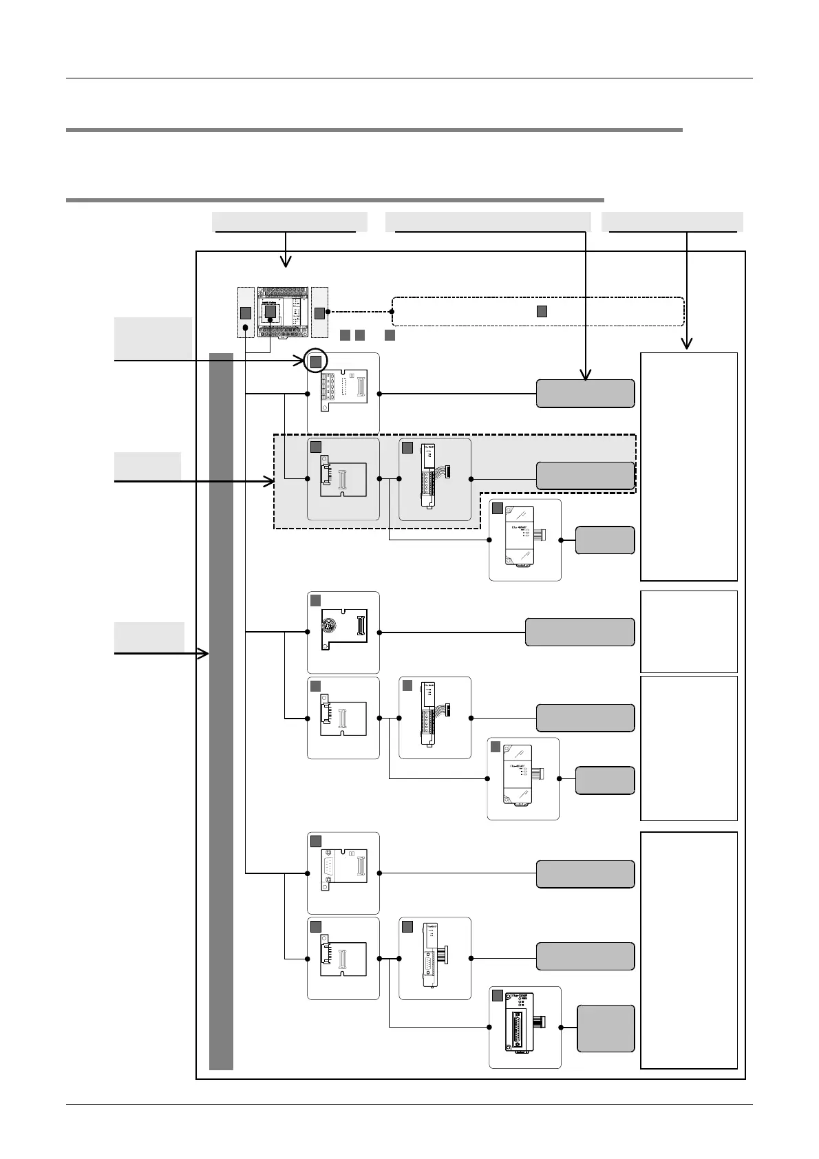
The block diagram below shows combinations of optional communication equipment applicable in each FX Series.
2.3.1 How to look at combination pages
, and indicate the mounting position.
FX
1N
Series
A
C
One line can be selected.
N:N Network
Parallel link
Computer link
Non-protocol
communication
Programming
communication
Computer link
Non-protocol
communication
Programming
communication
Remote
maintenance
FX
0N
-232ADP
A
FX
1N-
232-BD
B
FX
1N
-CNV-BD
B
FX
2NC
-232ADP
A
9-pin D-Sub,
male
25-pin
D-Sub,
female
9-pin D-Sub,
male
RS-485
RS-232C
RS-422
Non-protocol
communication
FX
1N
-422-BD
B
FX
1N
-CNV-BD
B
FX
2NC
-485ADP
A
FX
0N
-485ADP
A
8-pin MINI-DIN,
female
M3 terminal
block
European
terminal block
FX
2NC
-485ADP
A
FX
0N
-485ADP
A
FX
1N-
485-BD
B
FX
1N
-CNV-BD
B
European
terminal block
M3 terminal
block
European
terminal block
A B C
(For the mounting procedure, refer to the
respective communication equipment manual.)
For special function units/blocks , refer to the next page.
B
FX PLC main
unit mounting
position
Selection
example
Connection
condition
FX Series name
Communication equipment connection type Applicable communication type
C

 Loading...


