B-27
FX Series PLC User's Manual - Data Communication Edition
N:N Network
6 Test Run (Communication Test)
6.2 Creating Programs for the Communication Testing
A
Common Items
B
N:N Network
C
Parallel Link
D
Computer Link
E
Inverter
Communication
F
Non-Protocol
Communication
(RS/RS2 Instruction)
G
Non-Protocol
Communication
(FX
2N
-232IF)
H
Programming
Communication
I
Remote
Maintenance
Apx.
Discontinued
models
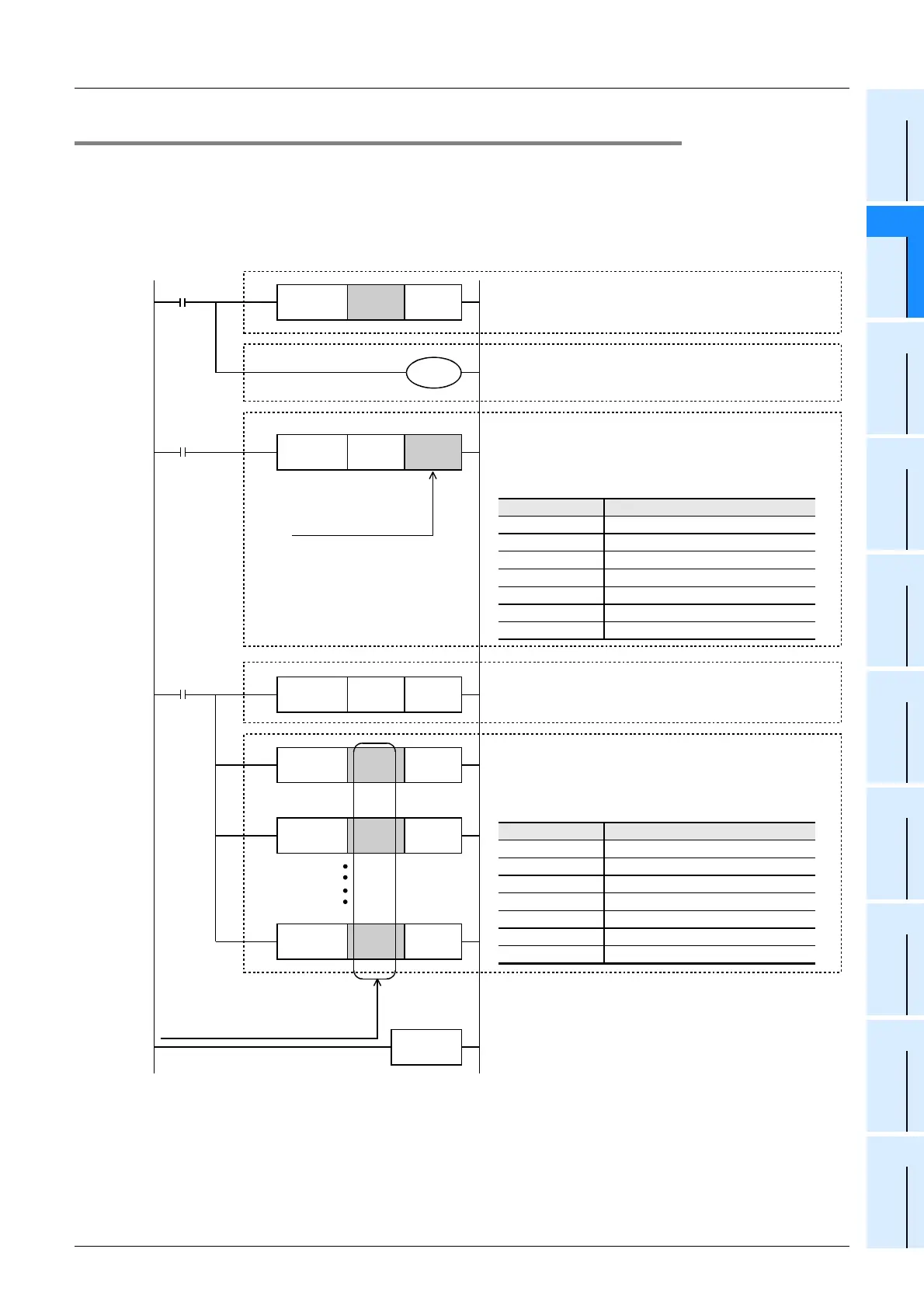
6.2.2 Creating a program for each slave station.
Create the program shown below for the communication test. (This program is not required during actual
operation.)
Determine the station number of each slave station, and then transfer a program corresponding to the station
number to each slave station.
Assign station numbers from "1" in the ascending order. (Use one station number only once. Do not skip
station numbers.)
Cautions
1) When using a PLC (such as an FX
1S Series PLC) with a small number of outputs, transfer information
from slave stations to auxiliary relays (M), etc., and then monitor the auxiliary relays using a programming
tool. (Example: Change "K1Y004" to "K1M4".)
2) In the circuit from step 14, specify link devices for other slave stations.
FNC 12
MOV
K1 D8176
0
M8000
FNC 12
MOV
K1X000 D10
FNC 12
MOV
D0 K1Y000
END
M8000
FNC 12
MOV
D20 K1Y010
8
14
FNC 12
MOV
D70 K1Y034
FNC 12
MOV
D30 K1Y014
Set the slave station number to D8176.
The setting range is from K1 to K7.
Step for writing information from a slave station (slave
station
→
master station)
Transfer the contents of X000 to X003 in this slave station
to a link device. The link device varies depending on the
station number.
The table below shows the link devices to be used:
Steps for reading information from another slave station
(another slave stations
→
this slave station)
By using link devices, read information from all other slave
stations.
The table below shows the link devices to be used:
Step for reading information from the master station (master
station
→
slave station)
The contents of X000 to X003 in the master station are
transferred to outputs (Y) in this slave station.
Specify the link device
number for this slave
station.
Specify link device numbers for
other slave stations. (Do not specify
the device number (D10) for this
slave station.)
When using ch1, this step is not required.
When using ch2, program "OUT M8179."
(Only in the FX
3U
and FX
3UC
)
M8179
M8038
Output (Y)
Y004 to Y007
Y010 to Y013
Y014 to Y017
Y020 to Y023
Y024 to Y027
Y030 to Y033
Y034 to Y037
Slave station No. Link device
1
2
3
4
5
6
7
D10
D20
D30
D40
D50
D60
D70
Output (Y)
Y004 to Y007
Y010 to Y013
Y014 to Y017
Y020 to Y023
Y024 to Y027
Y030 to Y033
Y034 to Y037
Slave station No. Link device
1
2
3
4
5
6
7
D10
D20
D30
D40
D50
D60
D70

 Loading...


