E-41
FX Series PLC User's Manual - Data Communication Edition
Inverter Communication
5 Communication Setting in Inverter
5.6 E700 Series (when PU port is connected)
A
Common Items
B
N:N Network
C
Parallel Link
D
Computer Link
E
Inverter
Communication
F
Non-Protocol
Communication
(RS/RS2 Instruction)
G
Non-Protocol
Communication
(FX
2N
-232IF)
H
Programming
Communication
I
Remote
Maintenance
Apx.
Discontinued
models
5.6.2 Parameter setting method (reference)
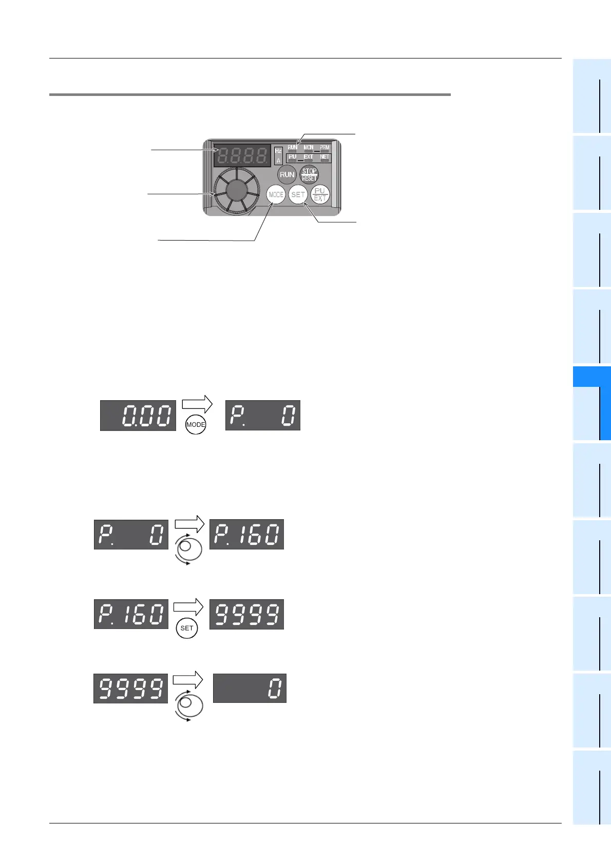
This subsection explains the parameter setting method using the operation panel.
For details on the operation panel, refer to the respective inverter manual.
The operating procedure example below shows a case in which the baud rate is set to 19200 bps.
1 Confirming the RUN indicator and the operation mode indicator
Confirm that the operation is stopped (that the RUN indicator is off).
2 Selecting the parameter setting mode
Press the MODE key, and select the parameter setting mode.
3 Setting the parameter Pr. 160 to "0"
(This step is not required if Pr. 160 is already set to "0".)
1. Turn the setting dial until "Pr. 160" is displayed.
2. Press the SET key to read the current set value.
3. Turn the setting dial, and change the set value to "0".
Operating status display
Lit or flicker during inverter operation
SET key
Determines each setting
MODE key
Used to change each setting mode
Monitor
(4-digit LED)
Show the frequency,
parameter number, etc.
Setting dial
Used to change
the frequency setting
and parameter values.
Monitor/frequency
setting mode
Parameter setting mode
The previously read parameter
is displayed.

 Loading...


