G-13
FX Series PLC User's Manual - Data Communication Edition
Non-Protocol Communication (FX2N-232IF)
4 Wiring
4.3 Connection to External Equipment with Terminal Specifications (with Control Line)
A
Common Items
B
N:N Network
C
Parallel Link
D
Computer Link
E
Inverter
Communication
F
Non-Protocol
Communication
(RS/RS2 Instruction)
G
Non-Protocol
Communication
(FX
2N
-232IF)
H
Programming
Communication
I
Remote
Maintenance
Apx.
Discontinued
models
4.3 Connection to External Equipment with Terminal Specifications
(with Control Line)
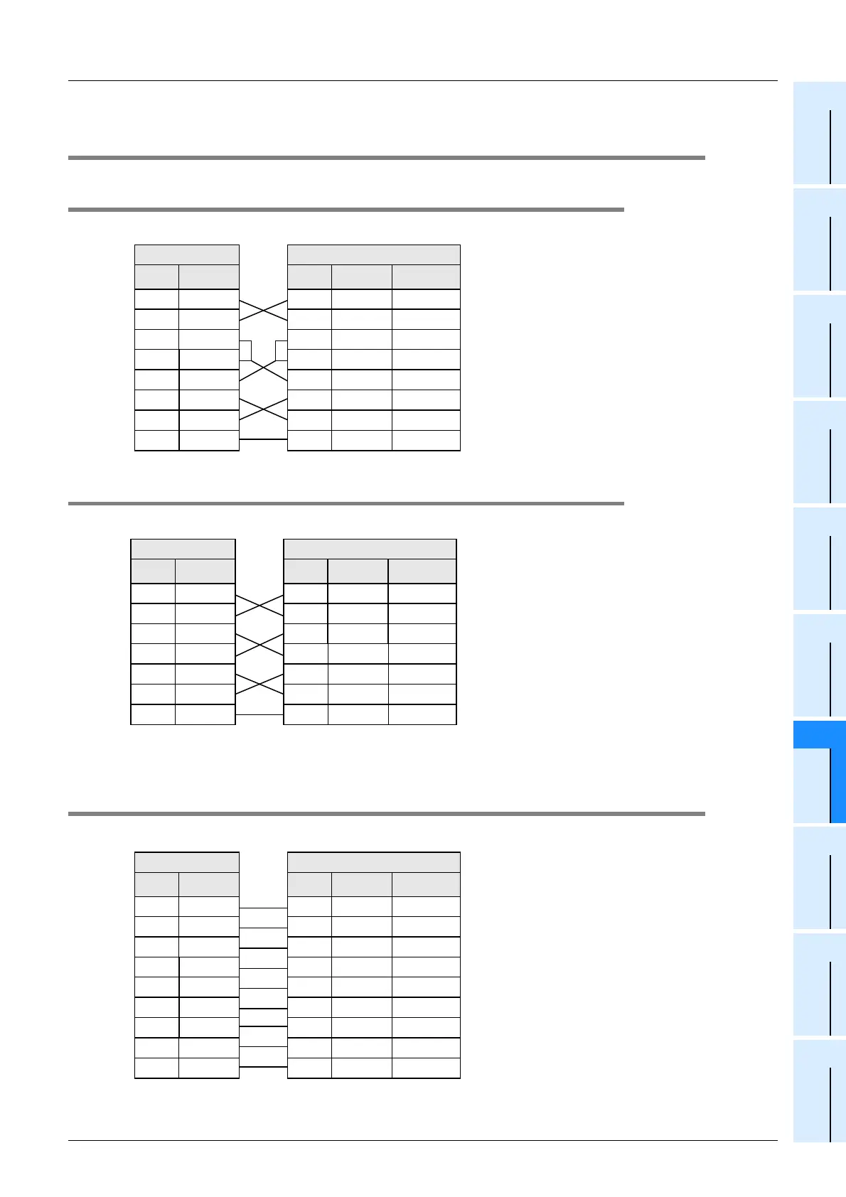
4.3.1 Standard RS-232C mode
Cross cable, BFM #0 (communication format): b9 = 0, b8 = 1 (standard RS-232C mode)
4.3.2 Interlink connection mode
Interlink serial cross cable, BFM #0 (communication format): b9 = 1, b8 = 1 (RS-232C interlink connection mode)
4.4 Connection to External Equipment with Modem Specifications
Straight cable, BFM #0 (communication format): b9 = 0, b8 = 1 (standard RS-232C mode)
PLC side
RS-232C external equipment side
Name
FX
2N
-232IF
Name
9-pin D-Sub 25-pin D-Sub
SD(TXD)
3
SD(TXD)
32
RD(RXD)
2
RD(RXD)
23
RS(RTS)
7
RS(RTS)
74
CS(CTS)
8
CS(CTS)
85
CD(DCD)
1
CD(DCD)
18
ER(DTR)
4
ER(DTR)
420
DR(DSR)
6
DR(DSR)
66
SG(GND)
5
SG(GND)
57
*1 *1
*2*2
When the FX2N-232IF receives the RS (request
to send) signal at its carrier to send (CS) pin, the
FX
2N-232IF transfers signals as if the external
equipment exists.
*1. It is not necessary to connect the CD signal if
monitoring the CD signal is not required.
For the CD signal, the 232IF indicates only the
status.
*2. The 232IF indicates only the status.
PLC side
RS-232C external equipment side
Name Name
9-pin D-Sub 25-pin D-Sub
SD(TXD)
3
SD(TXD)
32
RD(RXD)
2
RD(RXD)
23
RS(RTS)
7
RS(RTS)
74
CS(CTS)
8
CS(CTS)
85
ER(DTR)
4
ER(DTR)
420
DR(DSR)
6
DR(DSR)
66
SG(GND)
5
SG(GND)
57
*1 *1
*2*2
FX
2N
-232IF
In the interlink connection mode, the 232IF can
receive data larger than 512 bytes which is the
upper limit of the received data buffer in the
232IF.
*1. In this mode, the request to send (RS) signal works
as the receiving enable signal for the 232IF.
When the 232IF receives data beyond the
maximum number of receivable bytes, it turns OFF
which works as the receive ready signal (RS signal)
to ask the external equipment to stop sending. At
this time, by withdrawing the data located in the
received data buffer using a sequence program,
the 232IF can receive remaining data.
PLC side
RS-232C external equipment side
Name Name
9-pin D-Sub 25-pin D-Sub
SD(TXD)
3
SD(TXD)
32
RD(RXD)
2
RD(RXD)
23
RS(RTS)
7
RS(RTS)
74
CS(CTS)
8
CS(CTS)
85
CD(DCD)
1
CD(DCD)
18
ER(DTR)
4
ER(DTR)
420
DR(DSR)
6
DR(DSR)
66
SG(GND)
5
SG(GND)
57
CI(RI)
9
CI(RI)
922
*3 *3
*2 *2
*1 *1
FX
2N
-232IF
*1. It is not necessary to connect the CD signal if
monitoring the CD signal is not required.
For the CD signal, the 232IF indicates only the
status.
*2. The 232IF indicates only the status.
*3. It is not necessary to connect the CI signal if
monitoring of the CI signal is not required. For the
CI signal, the 232IF indicates only the status.

 Loading...


