E-4
FX Series PLC User's Manual - Data Communication Edition
Inverter Communication
1 Outline
1.2 Procedures Before Operation
1.2 Procedures Before Operation
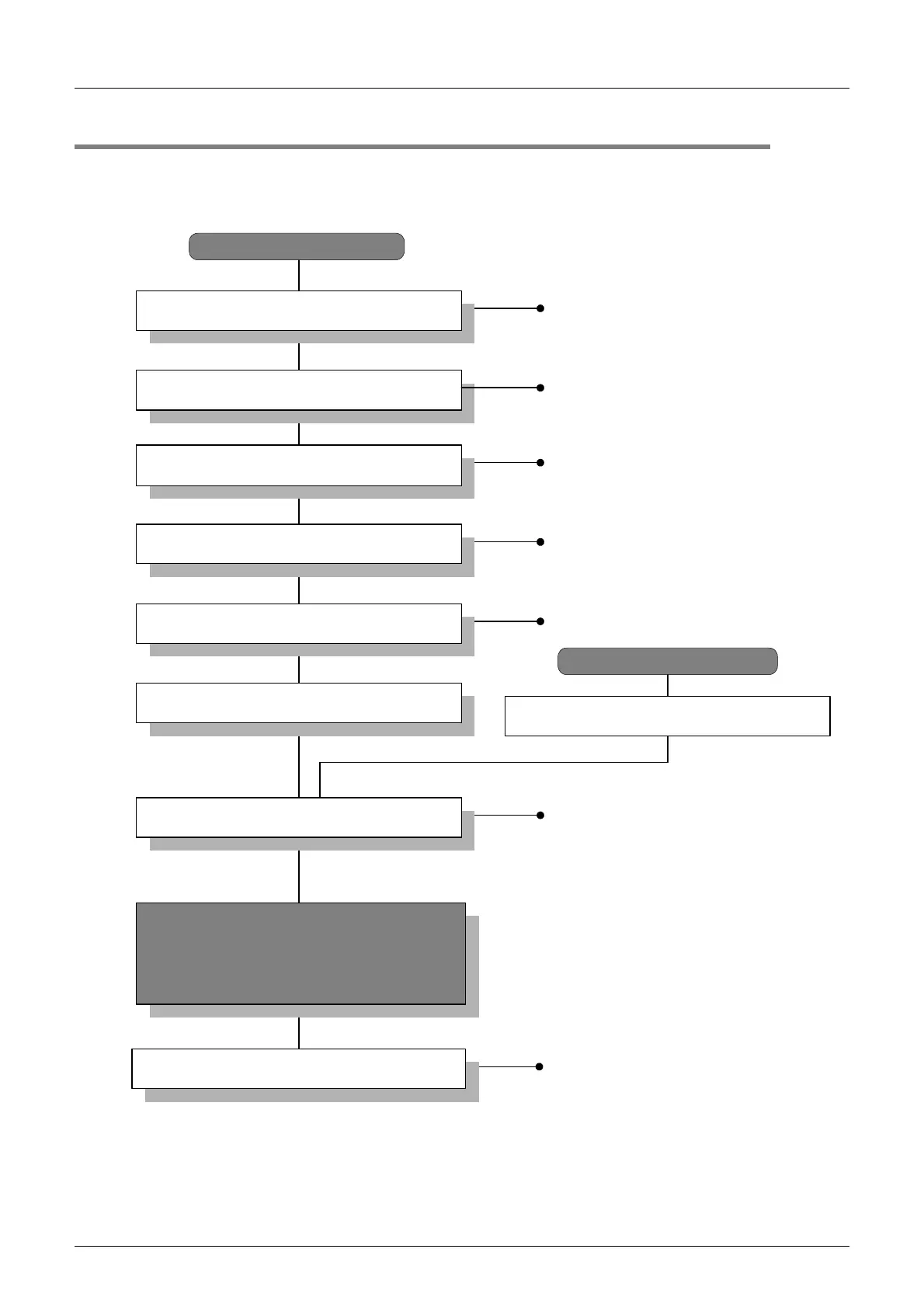
The flow chart below shows the Inverter Communication setting and sequence programs creation procedures
up until data link:
Communication specifications
• Applicable inverters
• Operation commands and parameters
Check communication specifications
Inverter Communication
System configuration
• Select communication equipment
Wiring procedure
• Selection of cables and connection
equipment
• Wiring example
Outline of system
• Available PLC versions
• Available programming tools
Refer to Chapter 1
Perform PLC communication setting
Refer to Chapter 6
Refer to Chapter 4
Refer to Chapter 5
Program examples for FX
2N
/FX
2NC
Series
(Chapter 8)
• Basic programs
Program examples for FX
3U
/FX
3UC
Series
(Chapter 10)
• Basic programs
Practical program examples
Programs for FX
2N
/FX
2NC
Series
(Chapter 7)
• Common items
• Basic programs
Programs for FX
3U
/FX
3UC
Series
(Chapter 9)
• Common items
• Basic programs
Refer to Chapter 7, 9
Based on SD/RD lamp lighting status and
contents of error check devices, verify that
communication is being executed normally.
If there are problems, refer to the troubleshooting
(Chapter 11).
Refer to Chapter 8, 10
Programming tool
Connect PLC
*1
*1 For the programming tool to PLC connection procedure, refer to the "Programming Communication" section in
this manual or the respective programming tool manual.
For details on operation method, refer to the respective pro
rammin
tool manual.
Parameter communication
Refer to Chapter 2
Refer to Chapter 3
Determine system configuration and selection
Perform wiring
Set inverter communication
Create programs
Outline

 Loading...


