E-52
FX Series PLC User's Manual - Data Communication Edition
Inverter Communication
7 Creating Programs (for FX2N and FX2NC PLCs)
7.2 Common Items in Inverter Communication Instructions
7.2 Common Items in Inverter Communication Instructions
7.2.1 Inverter communication types (EXTR K10 to K13)
An FX2N/FX2NC PLC and inverter execute communication using EXTR (FNC180) instruction.
EXTR instruction can be described in four types of methods, from "EXTR K10" to "EXTR K13", depending on
the data communication direction and parameter writing/reading direction.
7.2.2 Function and operation
1. Communication start timing
At the rising edge (OFF→ON) of the drive condition, the PLC starts communication with an inverter.
Even if the drive condition turns OFF during communication with an inverter, the PLC executes
communication until the end.
When the drive condition is always ON, the PLC executes communication repeatedly.
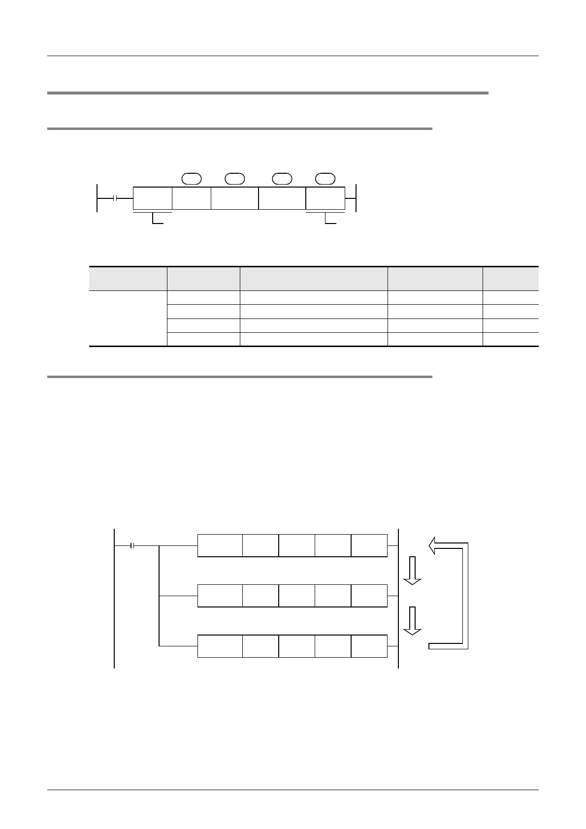
2. Simultaneous driving of EXTR instructions and communication processing
1) Driving instructions at the same time
- Two or more EXTR functions (K10 to K13) can be programmed, and driven at the same time.
- When two or more instructions are driven at the same time during communication, the next EXTR
instruction in the program is executed after the current communication with an inverter is finished.
Instruction
Function
number (S)
Function Control direction
Detailed
explanation
EXTR(FNC180)
K10 Monitors inverter operations PLC ← inverter 7.3
K11 Controls inverter operations PLC → inverter 7.4
K12 Reads inverter parameters PLC ← inverter 7.5
K13 Writes inverter parameters PLC → inverter 7.6
FNC180
EXTR
Function
number
Inverter station
number
Inverter
instruction code
Read/
Write
S S
1
S
2
S
3
Only EXTR (16-bit type) is applicable.
DEXTR (32-bit type), EXTRP (pulse type)
and DEXTRP (32-bit pulse type) are not
applicable.
Read value storage
destination or value written
to inverter
M8000
FNC180
EXTR
FNC180
EXTR
FNC180
EXTR
(1)
(2)
(3)
M8155
ON
→
OFF
M8155
ON
→
OFF
M8155
ON
→
OFF
RUN
monitor

 Loading...


