D-12
FX Series PLC User's Manual - Data Communication Edition
Computer Link
2 Specifications
2.2 Link Specifications
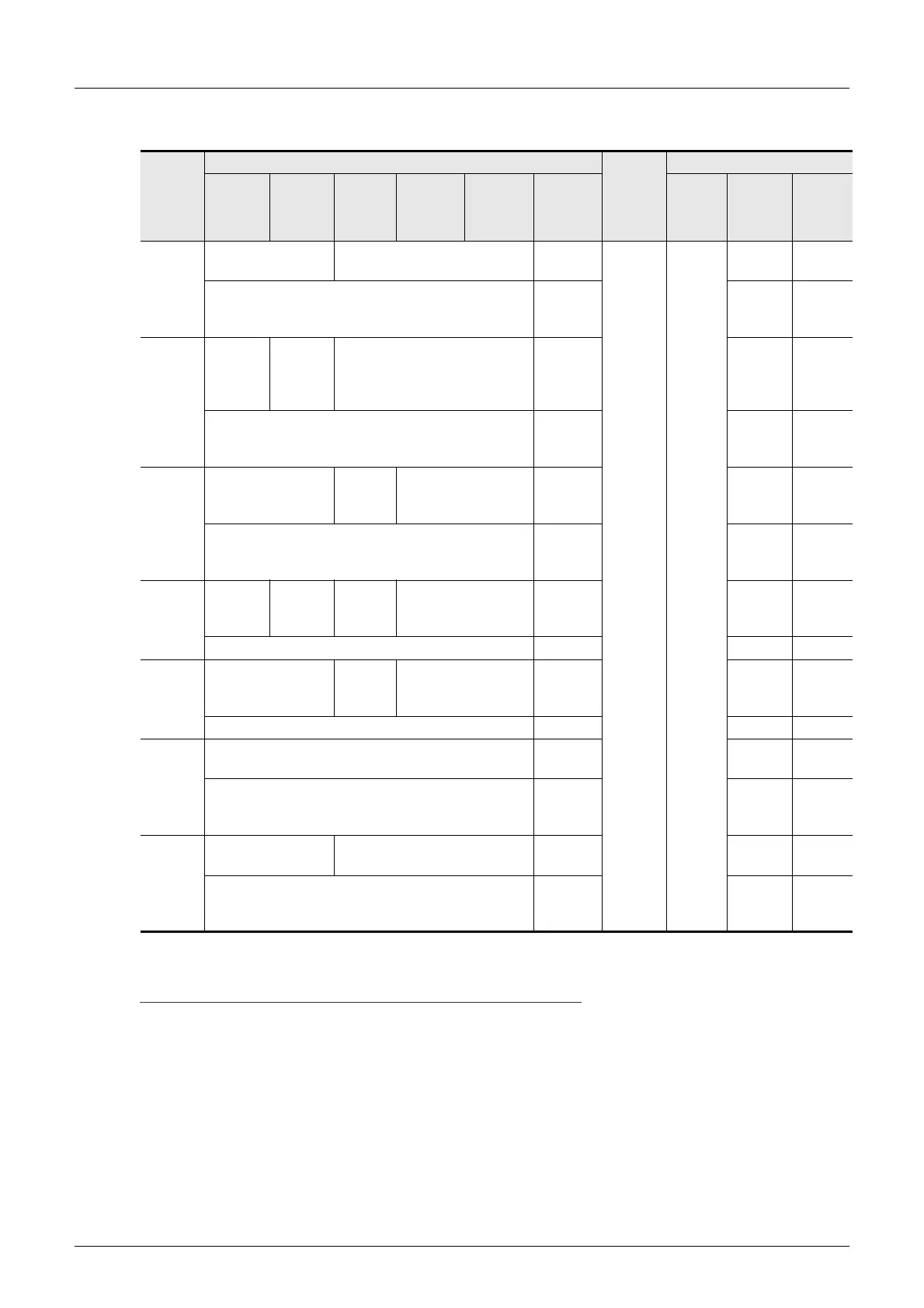
2. Word devices
*1. The WT and QT commands do not support 32-bit counters (C200 to C255).
Cautions
1) When using bit devices in a command requiring specification in 1-word units, make sure that the head
device number is a multiple of "8".
2) Special auxiliary relays and special data registers are classified into ones for read only, write only and
ones for system only.
If data is written to any range in which writing is not allowed, an error may occur in the PLC.
For details on special auxiliary relays and special data registers, refer to the manual of the PLC.
3) In FX
1S, FX1N, FX2N, FX3U, FX1NC, FX2NC and FX3UC PLCs, the PLCs cannot access the program area
(in the built-in RAM and memory cassette) when users set file registers (D).
In FX
3U and FX3UC PLCs, extension registers (R) cannot access extension file registers (ER) in a
mounted memory cassette.
Device
Device number range (character)
Device
number
expression
Decimal/
Octal
Available commands
FX1S FX0N
FX2(FX),
FX
2C
FX1N,
FX
1NC
FX2N,
FX
2NC
FX3U,
FX
3UC
BR,
BW, BT
WR,
WW, WT
QR,
QW, QT
Timer
current
value
(T)
TN000 to TN063 TN000 to TN255
TN000 to
TN511
Decimal —
—
—
TN00000
to
TN00511
—
Counter
current
value
(C)
CN000 to
CN031
CN235 to
CN255
CN000 to
CN031
CN235 to
CN254
CN000 to CN255
CN000 to
CN255
*1
—
—
CN00000
to
CN00255
—
*1
Data
register
(D)
D0000 to D0255
D0000
to
D0999
D0000 to D7999
D0000 to
D7999
—
—
D000000
to
D007999
—
File
register
(D)
—
D1000 to
D2499
D1000
to
D2999
—— —
————
RAM
file
register
(D)
—
D6000
to
D7999
—— —
————
Exten-
sion
register
(R)
—
R0000 to
R9999
—
—
R000000
to
R032767
—
Special
data
register
(D)
D8000 to D8255 D8000 to D8255
D8000 to
D8511
—
—
D008000
to
D008511
—

 Loading...


