F-43
FX Series PLC User's Manual - Data Communication Edition
Non-Protocol Communication (RS/RS2 Instruction)
6 Creating Programs (RS Instruction)
6.3 Operation of Control Line
A
Common Items
B
N:N Network
C
Parallel Link
D
Computer Link
E
Inverter
Communication
F
Non-Protocol
Communication
(RS/RS2 Instruction)
G
Non-Protocol
Communication
(FX
2N
-232IF)
H
Programming
Communication
I
Remote
Maintenance
Apx.
Discontinued
models
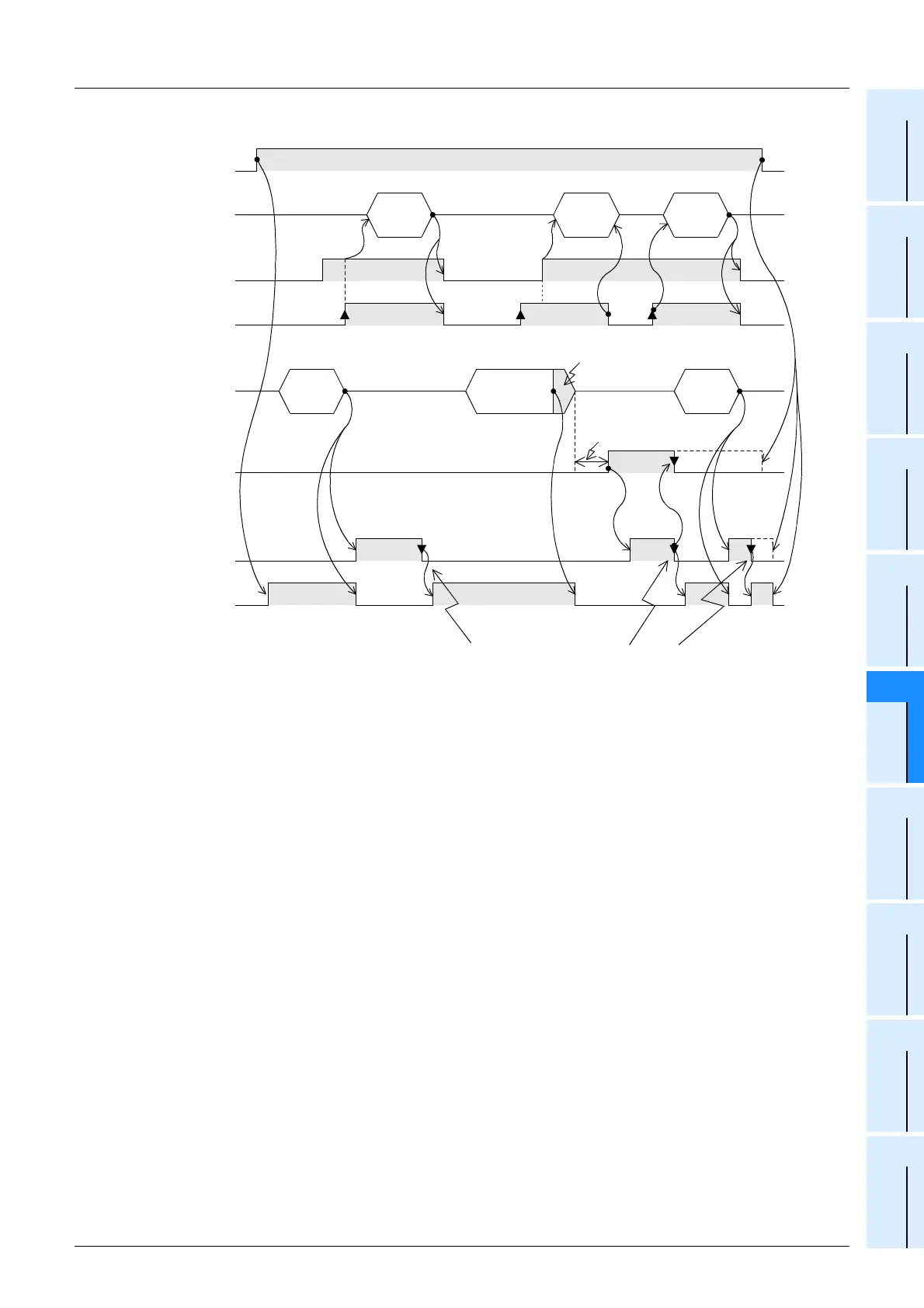
4. When the control line is in the interlink mode
*1. On the external equipment side, set the DR (DSR) signal to ON when the external equipment is ready
to receive.
The FX
2N, FX3U, FX2NC or FX3UC PLC sends the send data when both the DR (DSR) signal and the
sending request turn ON.
*2. In the interlink mode, the PLC sets ER (DTR) signal to OFF 30 characters before reaching the
specified amount of received data, and asks the external equipment to stop sending. After that, the
PLC can only receive up to 30 characters. In this case, temporarily stop sending, and then send the
remaining data after the ER (DTR) signal turns ON again.
When sending is stopped, the PLC finishes receiving after the time-out time setting is reached.
When sending is not stopped, the PLC finishes receiving after it has received the final send data or 30
characters. Accordingly, make sure that the amount of received data is "30 + α".
RS
instruction
driving
SD (TXD)
Send data
OFF ON
OFFON
Sending
request
M8122
Receiving
complete
M8123
RD (RXD)
Receive data
OFF ON
*1 *1 *1
Time-out
time setting
D8129
×
10 ms
OFF ON ON ON
Reset it in a sequence program.
While it remains ON, the PLC cannot receive the next set of data.
OFFON
DR (DSR)
Time-out
check flag
M8129
Up to 30 characters can be
received.
*2
ER (DTR)
Message
2
Message
4
Message
4
Message
3
Message 3
Message
1

 Loading...


