F-48
FX Series PLC User's Manual - Data Communication Edition
Non-Protocol Communication (RS/RS2 Instruction)
8 Creating Programs (RS2 Instruction)
8.1 Checking Contents of Related Devices
2. Word devices
R: Read only
R/W: Read or Write
Device
Name Description R/W
ch1 ch2
D8063 D8438
Serial communication
error code
When the serial communication error flag turns ON, this device
stores the corresponding error code.
R/W
D8400 D8420
Communication format
setting
This device sets the communication format. R/W
D8402 D8422
Amount of remaining
send data
This device stores the amount of remaining send data. R
D8403 D8423
Amount of data already
received
This device stores the amount of data already received. R
D8405 D8425
Communication
parameter display
This devices stores communication parameters set in the PLC. R
D8409 D8429 Time-out time setting This device sets the timeout time. R/W
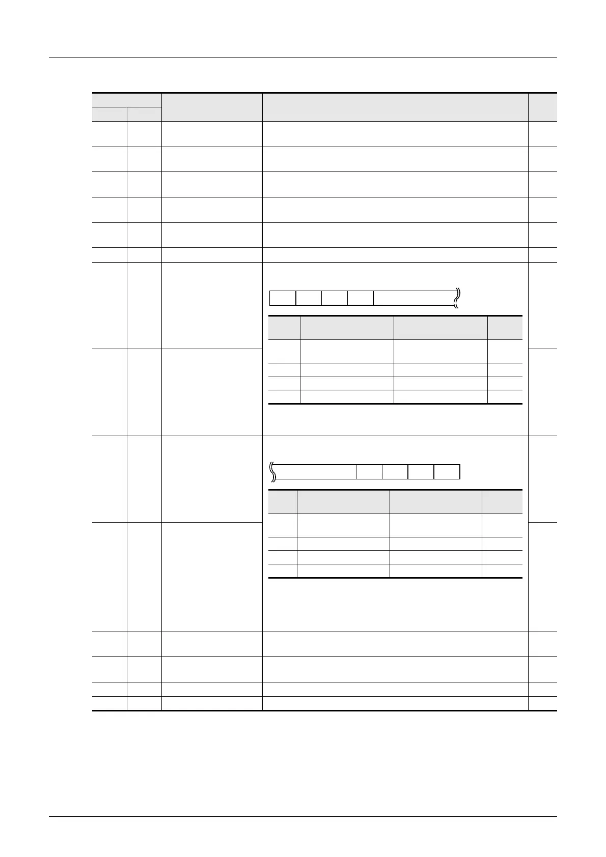
D8410 D8430 Header 1 and header 2
These devices set the headers 1 to 4.
When "H00" is set to the header 1, headers are not provided.
The area before H00 (in 1-byte units) is used to set the headers.
R/W
D8411 D8431 Header 3 and header 4 R/W
D8412 D8432
Terminator 1 and
terminator 2
These devices set the terminators 1 to 4.
When "H00" is set to the terminator 1, terminators are not
provided.
The area before H00 (in 1-byte units) is used to set the
terminators.
R/W
D8413 D8433
Terminator 3 and
terminator 4
R/W
D8414 D8434
Receiving sum (receive
data)
This device stores the received sum check value. R
D8415 D8435
Receiving sum
(calculation result)
This device stores the sum check value calculated from the
received data.
R
D8416 D8436 Sending sum This device stores the sum check value added to the send data. R
D8419 D8439 Operation mode display This device stores the current communication being executed. R
1 2 3 4Data
Header
Header
ch1 ch2
Initial
value
1
D8410 (lowest-order byte) D8430 (lowest-order byte)
H02
(STX)
2
D8410 (highest-order byte) D8430 (highest-order byte)
H00
3
D8411 (lowest-order byte) D8431 (lowest-order byte)
H00
4
D8411 (highest-order byte) D8431 (highest-order byte)
H00
1 2 3 4Data
Terminator
Termi-
nator
ch1 ch2
Initial
value
1
D8412 (lowest-order byte) D8432 (lowest-order byte)
H03
(ETX)
2
D8412 (highest-order byte) D8432 (highest-order byte)
H00
3
D8413 (lowest-order byte) D8433 (lowest-order byte)
H00
4
D8413 (highest-order byte) D8433 (highest-order byte)
H00

 Loading...


