G-21
FX Series PLC User's Manual - Data Communication Edition
Non-Protocol Communication (FX2N-232IF)
5 Creating Programs
5.4 Buffer Memory (BFM)
A
Common Items
B
N:N Network
C
Parallel Link
D
Computer Link
E
Inverter
Communication
F
Non-Protocol
Communication
(RS/RS2 Instruction)
G
Non-Protocol
Communication
(FX
2N
-232IF)
H
Programming
Communication
I
Remote
Maintenance
Apx.
Discontinued
models
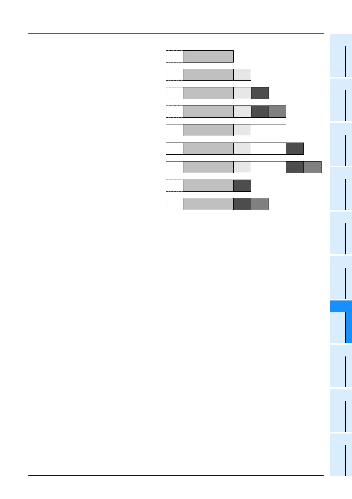
1. Communication format
Select the communication format to
be used to send and receive data in
the 232IF from the formats shown to
the right.
1) The header can be specified
before the data in the
communication format.
2) In the communication format [1],
hexadecimal (binary) values and
ASCII codes can be sent and
received.
When using the communication
formats [2] to [9], make sure to use
ASCII codes as the sent and
received data.
The received data should not
include the header, terminator or
CR. (In communication formats [4],
[7] and [9], the data area after "CR"
is not received.)
By specifying b13 and b12 of BFM
#0, the ASCII-Hexadecimal
conversion function can be used
for communication.
3) ASCII codes "01H" to "1FH" can be used as the head terminator.
4) In the RS-232C interlink connection mode, the communication formats [2] to [7] are valid.
2. b0 to b7 (data length, parity, stop bit and baud rate)
Align the setting of b0 to b7 with the communication specifications in the connected external equipment.
3. b9 and b8 (control line)
1) When "control line not provided (b9 = 0, b8 = 0)" is specified, data is transferred using only the SD and
RD signals without using the control line.
2) When the "standard RS-232C mode (b9 = 0, b8 = 1)" is specified, use a cross cable to connect
equipment with the terminal specifications, and use a straight cable to connect equipment with the
modem specifications.
3) When the "RS-232C interlink connection mode (b9 = 1, b8 = 1)" is specified, the sending request (RS)
signal works as the receiving enable signal for the 232IF. When the 232IF receives data beyond the
maximum number of receivable bytes (BFM #2), it turns OFF the receiving enable (RS) signal to ask the
external equipment to suspend sending.
At this time, by withdrawing the contents of the received data buffer to data registers in the PLC using a
sequence program, the 232IF can continuously receive the remaining data.
When this mode is specified, make sure to perform the interlink connection for RS-232C.
→ For the wiring of equipment according to each setting, refer to Chapter 4.
→ For the operation of the control line, refer to Section 5.5.
4. b11 and b10 (CR and LF addition)
The following specification methods are applicable:
1) Both CR and LF are not added (b11 = 0, b10 = 0).
2) Only CR is added (b11 = 0, b10 = 1).
3) Both CR and LF are added (b11 = 1, b10 = 1).
For the CR/LF addition format, refer to the communication format list above.
Data
Data
[1]
Data CR
Data LF
Data
Data
Data Sum
Data
Data
Header
Header
Header
LFCR
Termi-
nator
Termi-
nator
CR LF
CR
Termi-
nator
Termi-
nator
CR
CR
Termi-
nator
Sum
Termi-
nator
Sum
[2]
[3]
[4]
[5]
[6]
[7]
[8]
[9]

 Loading...


