I-14
FX Series PLC User's Manual - Data Communication Edition
Remote Maintenance
3 System Configuration and Selection
3.2 Setting Applicable FX PLC and Communication Equipment
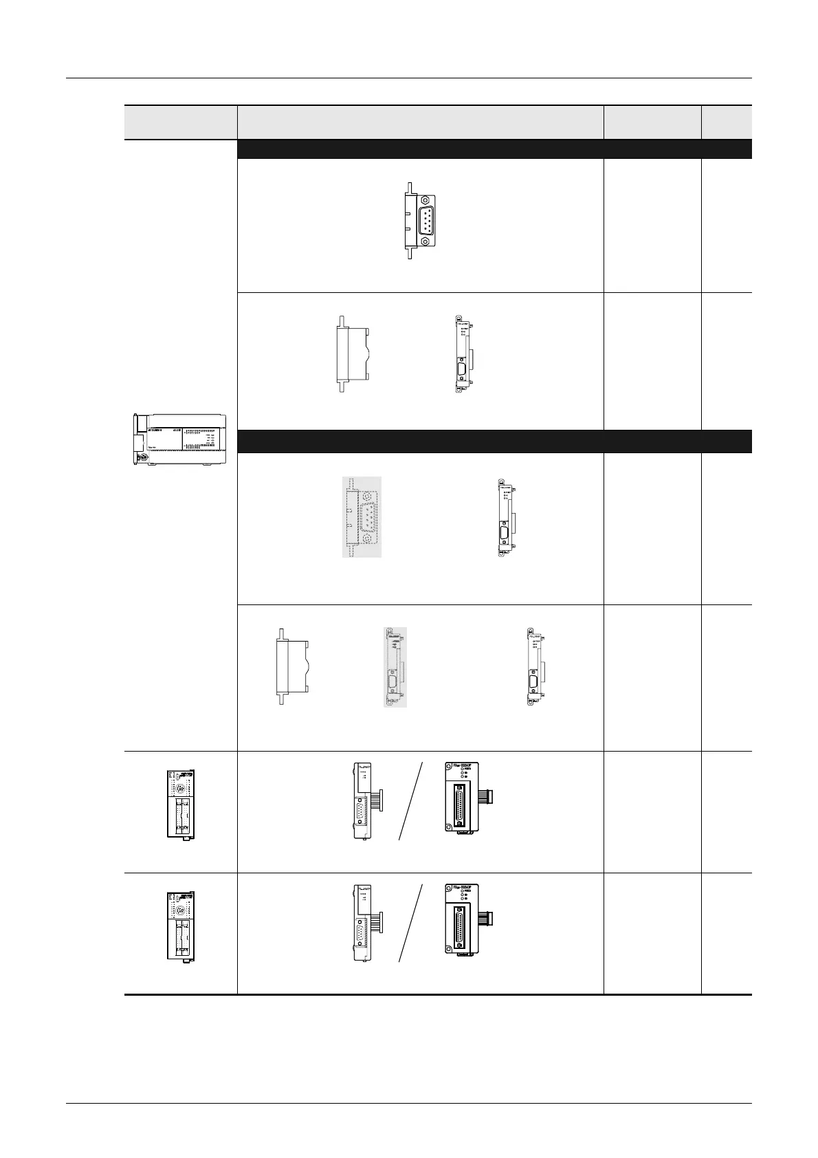
FX3U
When using channel 1 (ch 1)
15 m
(49' 2")
15 m
(49' 2")
When using channel 2 (ch 2)
*1
15 m
(49' 2")
15 m
(49' 2")
FX
1NC
15 m
(49' 2")
FX
2NC
15 m
(49' 2")
*1. When using ch2 in an FX3U PLC, it can be set only in the PP modem mode (ch2).
FX Series Communication equipment (option)
Total extension
distance
Check
FX
3U
-232-BD
(9-pin D-Sub, male)
RD
SD
ch1
FX
3U
-CNV-BD
+
FX
3U
-232ADP(-MB)
(9-pin D-Sub, male)
ch1
+
FX
3U
-232ADP(-MB)
(9-pin D-Sub, male)
ch2
RD
SD
ch1
FX
3U
-
-BD
(Where
represents
232, 422, 485 and USB)
FX
3U
-CNV-BD
+
ch1
+
FX
3U
-232ADP(-MB)
(9-pin D-Sub, male)
ch2
FX
3U
-
ADP(-MB)
(Where
represents
232 and 485)
FX
2NC
-232ADP
(9-pin D-Sub)
FX
0N
-232ADP
(25-pin D-Sub)
FX
2NC
-232ADP
(9-pin D-Sub)
FX
0N
-232ADP
(25-pin D-Sub)

 Loading...


