I-25
FX Series PLC User's Manual - Data Communication Edition
Remote Maintenance
5 How to Setup Modems on the PLC Side
5.1 Setting Using GX Developer
A
Common Items
B
N:N Network
C
Parallel Link
D
Computer Link
E
Inverter
Communication
F
Non-Protocol
Communication
(RS/RS2 Instruction)
G
Non-Protocol
Communication
(FX
2N
-232IF)
H
Programming
Communication
I
Remote
Maintenance
Apx.
Discontinued
models
1. AT command structure
For initializing a modem, use the AT command developed by Hayes.
The Hayes AT command is generally expressed in the following format:
For details on the AT command, refer to the manual of the modem to be used.
2. Input example of the AT command for initialization, Example: ATE0S0 = 2Q1&D0&M4\Q0\J0&W
5 Inputting "CR" and "LF"
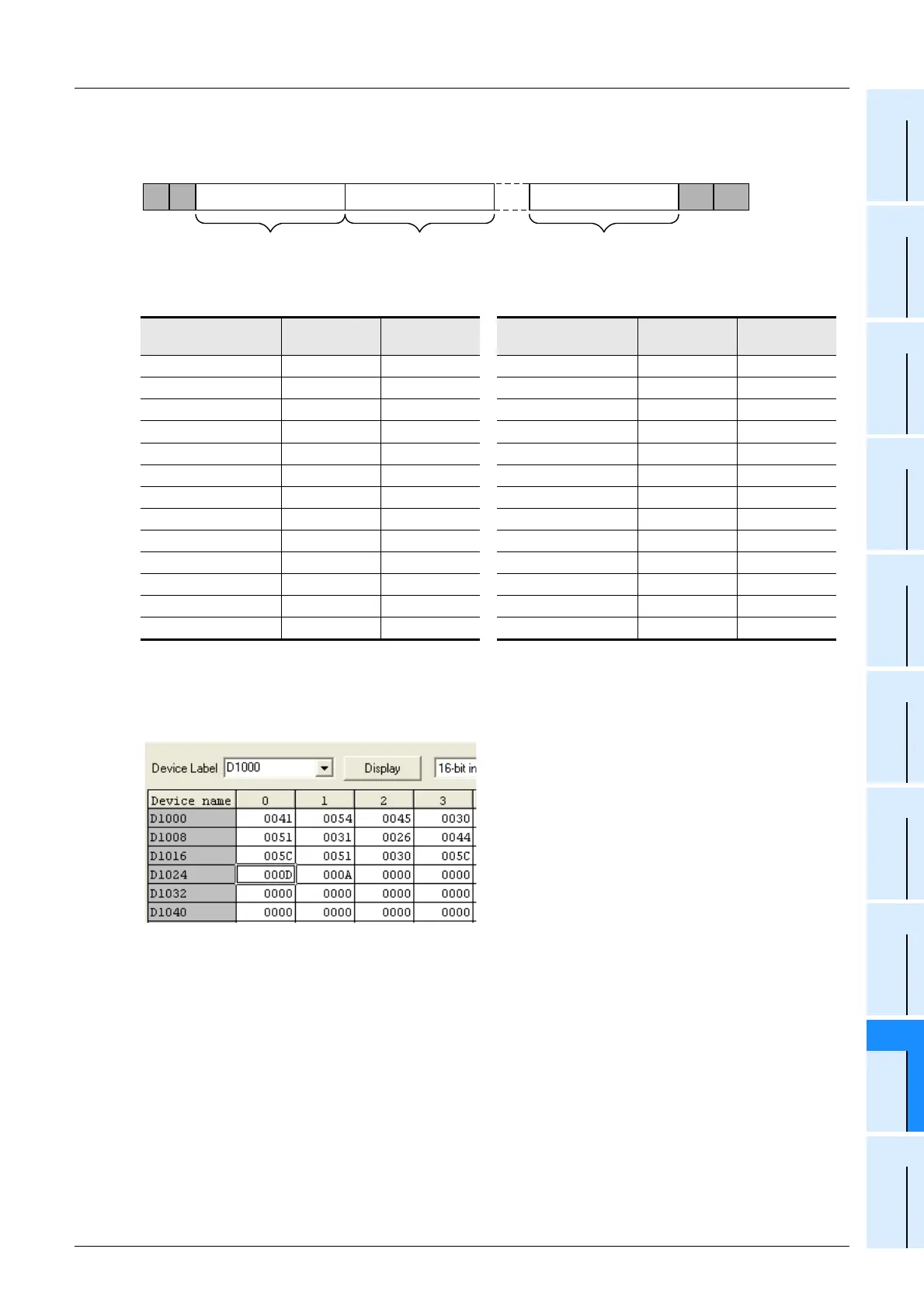
It is necessary to input "CR" and "LF" at the end of the AT command.
Input "000D" and "000A" (hexadecimal values) to data registers respectively.
If "CR (0DH)" and "LF (0AH)" are not input at the end of the AT command, remote maintenance is
not possible.
Data register No. ASCII code
Hexadecimal
value
Data register No. ASCII code
Hexadecimal
value
D1000 A 41 D1013 & 26
D1001 T 54 D1014 M 4D
D1002 E 45 D1015 4 34
D1003 0 30 D1016 \ 5C
D1004 S 53 D1017 Q 51
D1005 0 30 D1018 0 30
D1006 = 3D D1019 \ 5C
D1007 2 32 D1020 J 4A
D1008 Q 51 D1021 0 30
D1009 1 31 D1022 & 26
D1010 & 26 D1023 W 57
D1011 D 44 D1024 CR 0D
D1012 0 30 D1025 LF 0A
A T Command + Parameter Command + Parameter Command + Parameter CR LF
1 2 n......

 Loading...


