I-29
FX Series PLC User's Manual - Data Communication Edition
Remote Maintenance
5 How to Setup Modems on the PLC Side
5.2 Setting Using FXGP/WIN
A
Common Items
B
N:N Network
C
Parallel Link
D
Computer Link
E
Inverter
Communication
F
Non-Protocol
Communication
(RS/RS2 Instruction)
G
Non-Protocol
Communication
(FX
2N
-232IF)
H
Programming
Communication
I
Remote
Maintenance
Apx.
Discontinued
models
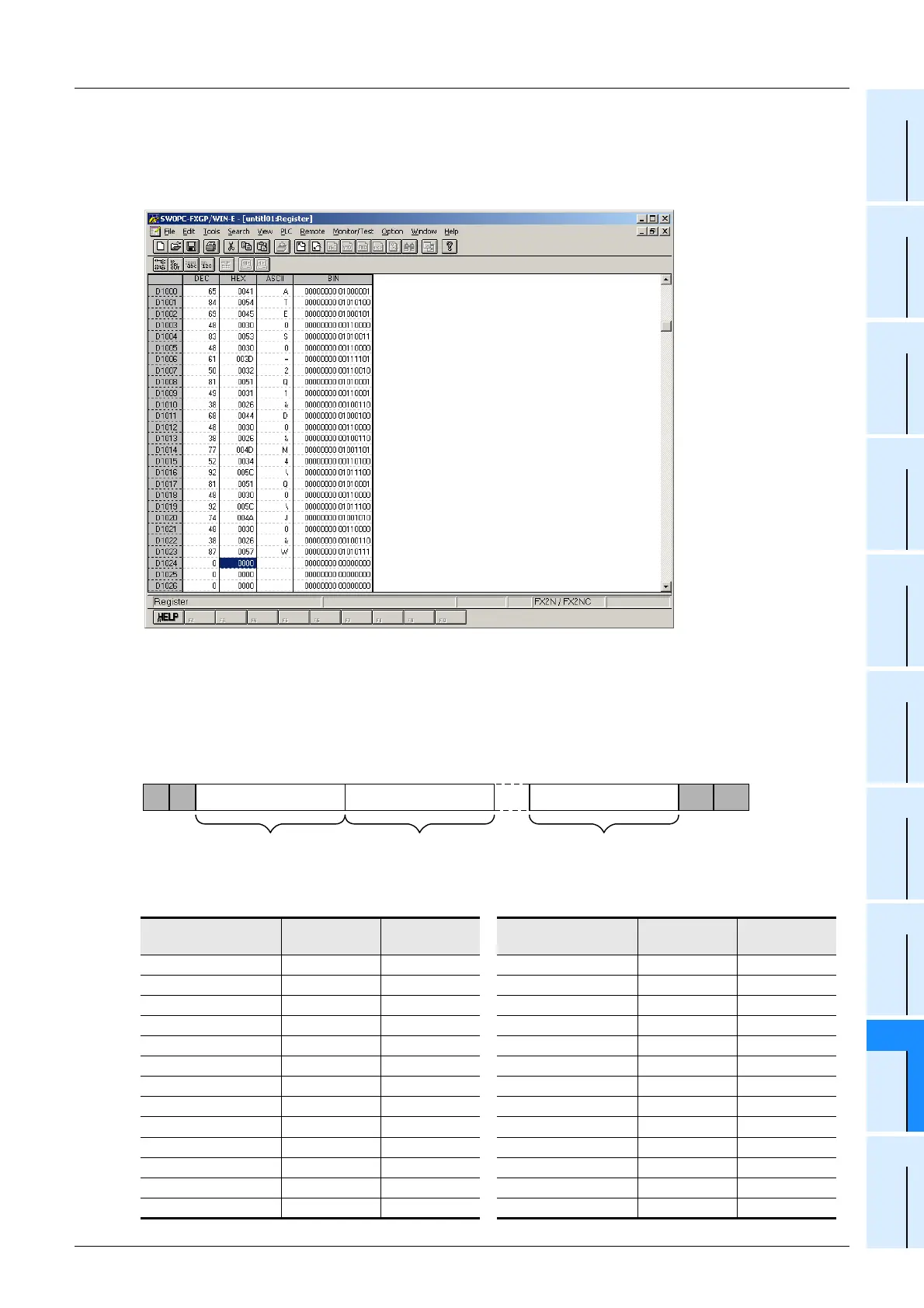
3 Inputting the AT command
Input the AT command to the "ASCII" column of D1000 and later. Input one (half-width) character to
one word.
Make sure to input "CR (0DH)" and "LF (0AH)" at the end of the AT command. If they are not input,
remote maintenance is not possible.
The "CR" and "LF" input method is explained in the next step.
1. AT command structure
For initializing a modem, use the AT command developed by Hayes.
The Hayes AT command is generally expressed in the following format:
For details on the AT command, refer to the manual of the modem to be used.
2. Input example of the AT command for initialization, Example: ATE0S0 = 2Q1&D0&M4\Q0\J0&W
Data register No. ASCII code
Hexadecimal
value
Data register No. ASCII code
Hexadecimal
value
D1000 A 41 D1013 & 26
D1001 T 54 D1014 M 4D
D1002 E 45 D1015 4 34
D1003 0 30 D1016 \ 5C
D1004 S 53 D1017 Q 51
D1005 0 30 D1018 0 30
D1006 = 3D D1019 \ 5C
D1007 2 32 D1020 J 4A
D1008 Q 51 D1021 0 30
D1009 1 31 D1022 & 26
D1010 & 26 D1023 W 57
D1011 D 44 D1024 CR 0D
D1012 0 30 D1025 LF 0A
A T Command + Parameter Command + Parameter Command + Parameter CR LF
1 2 n......

 Loading...


