Port Integration Module (S12GPIMV1)
MC9S12G Family Reference Manual Rev.1.27
230 NXP Semiconductors
2.4.3.48 Port J Interrupt Flag Register (PIFJ)
1
Read: Anytime
Write: Anytime
Table 2-73. PIEJ Register Field Descriptions
Field Description
7-0
PIEJ
Port J interrupt enable—
This bit enables or disables the edge sensitive pin interrupt on the associated pin. An interrupt can be generated if
the pin is operating in input or output mode when in use with the general-purpose or related peripheral function.
1 Interrupt is enabled
0 Interrupt is disabled (interrupt flag masked)
Address 0x026F (G1, G2) Access: User read/write
1
1
Read: Anytime
Write: Anytime, write 1 to clear
76543210
R
PIFJ7 PIFJ6 PIFJ5 PIFJ4 PIFJ3 PIFJ2 PIFJ1 PIFJ0
W
Reset00000000
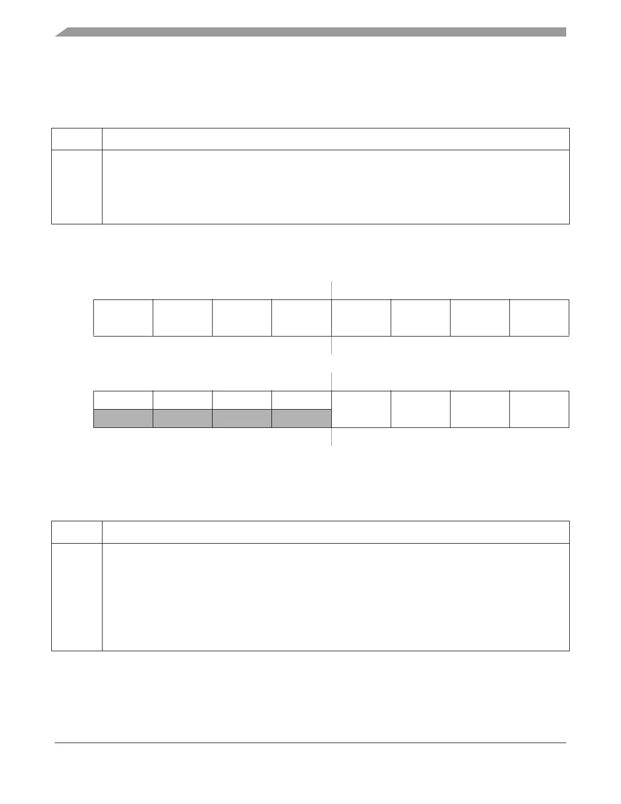
Address 0x026F (G3) Access: User read/write
1
76543210
R0000
PIFJ3 PIFJ2 PIFJ1 PIFJ0
W
Reset00000000
Figure 2-48. Port J Interrupt Flag Register (PIFJ)
Table 2-74. PIFJ Register Field Descriptions
Field Description
7-0
PIFJ
Port J interrupt flag—
This flag asserts after a valid active edge was detected on the related pin (see Section 2.5.4.2, “Pin Interrupts and
Wakeup”). This can be a rising or a falling edge based on the state of the polarity select register. An interrupt will
occur if the associated interrupt enable bit is set.
Writing a logic “1” to the corresponding bit field clears the flag.
1 Active edge on the associated bit has occurred
0 No active edge occurred

 Loading...


