RL78/G15 CHAPTER 6 TIMER ARRAY UNIT
R01UH0959EJ0110 Rev.1.10 Page 163 of 765
Mar 7, 2023
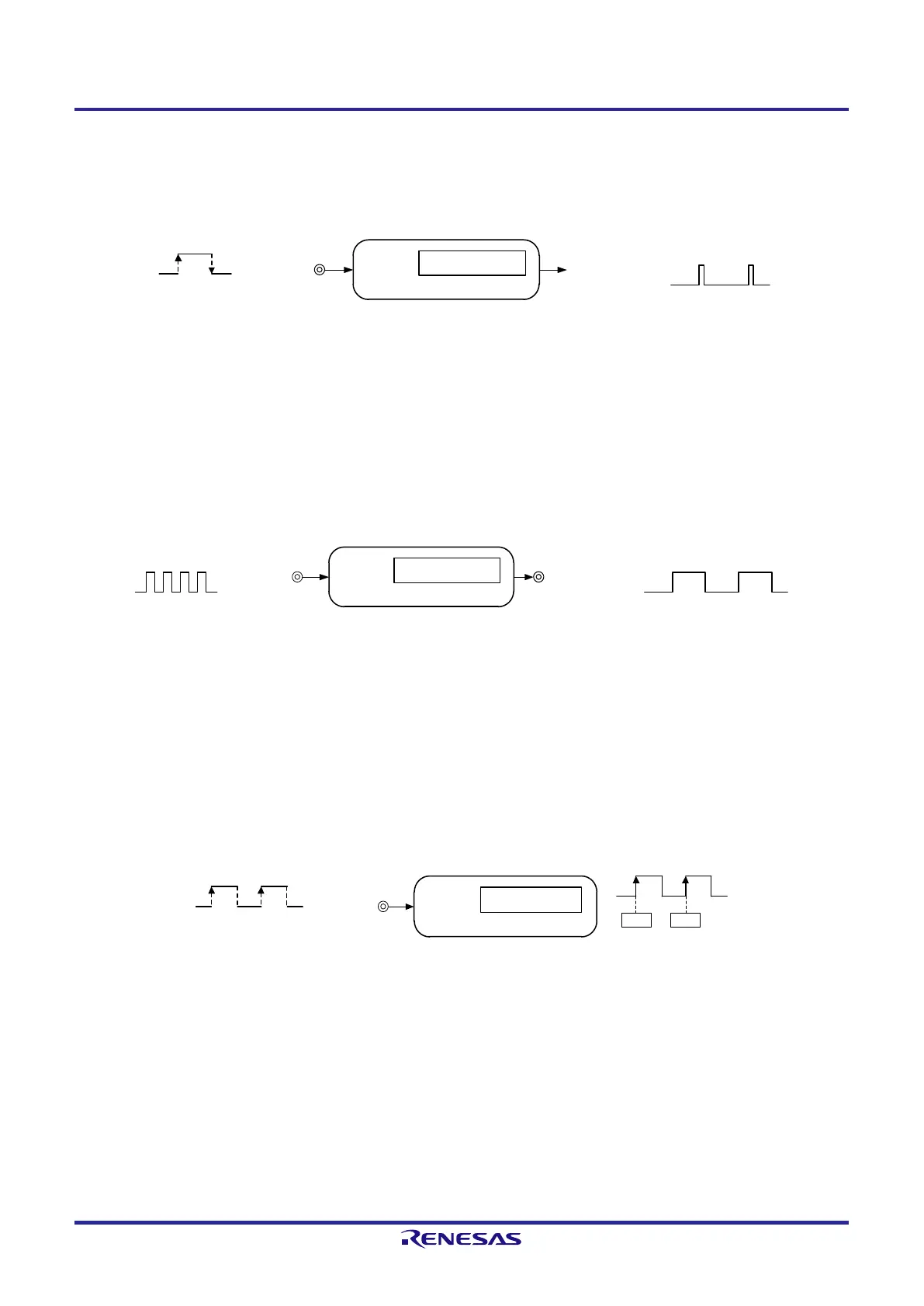
3) External event counter
Each timer of a unit can be used as an event counter that generates an interrupt when the number of the valid edges of a
signal input to the timer input pin (TImn) has reached a specific value.
Channel n
Interrupt signal
(
INTTMmn)
Compare operation
Timer input
(TImn
)
Edge detection
Remark 1. m: Unit number (m = 0), n: Channel number (n = 0 to 7)
Remark 2. The presence or absence of timer I/O pins of channel 0 to 7 depends on the product. See Table 6-2
Timer I/O Pins provided in Each Product for details.
4) Divider function (channels 0 and 3 only)
A clock input from a timer input pin (TI0n) is divided and output from an output pin (TO0n).
Channel n
Timer output
(TO0n)
Timer input
(TI0n)
Compare operation
Remark 1. n: Channel number (n = 0, 3)
Remark 2. The presence or absence of timer I/O pins of channels 0 and 3 depends on the product. See Table 6-2
Timer I/O Pins provided in Each Product for details.
5) Input pulse interval measurement
Counting is started by the valid edge of a pulse signal input to a timer input pin (TImn). The count value of the timer is
captured at the valid edge of the next pulse. In this way, the interval of the input pulse can be measured.
Channel n
Timer input
(TImn)
Capture operation
CaptureStart
00H xxH
Edge detection
Remark 1. m: Unit number (m = 0), n: Channel number (n = 0 to 7)
Remark 2. The presence or absence of timer I/O pins of channel 0 to 7 depends on the product. See Table 6-2
Timer I/O Pins provided in Each Product for details.
 Loading...


