RL78/G15 CHAPTER 6 TIMER ARRAY UNIT
R01UH0959EJ0110 Rev.1.10 Page 164 of 765
Mar 7, 2023
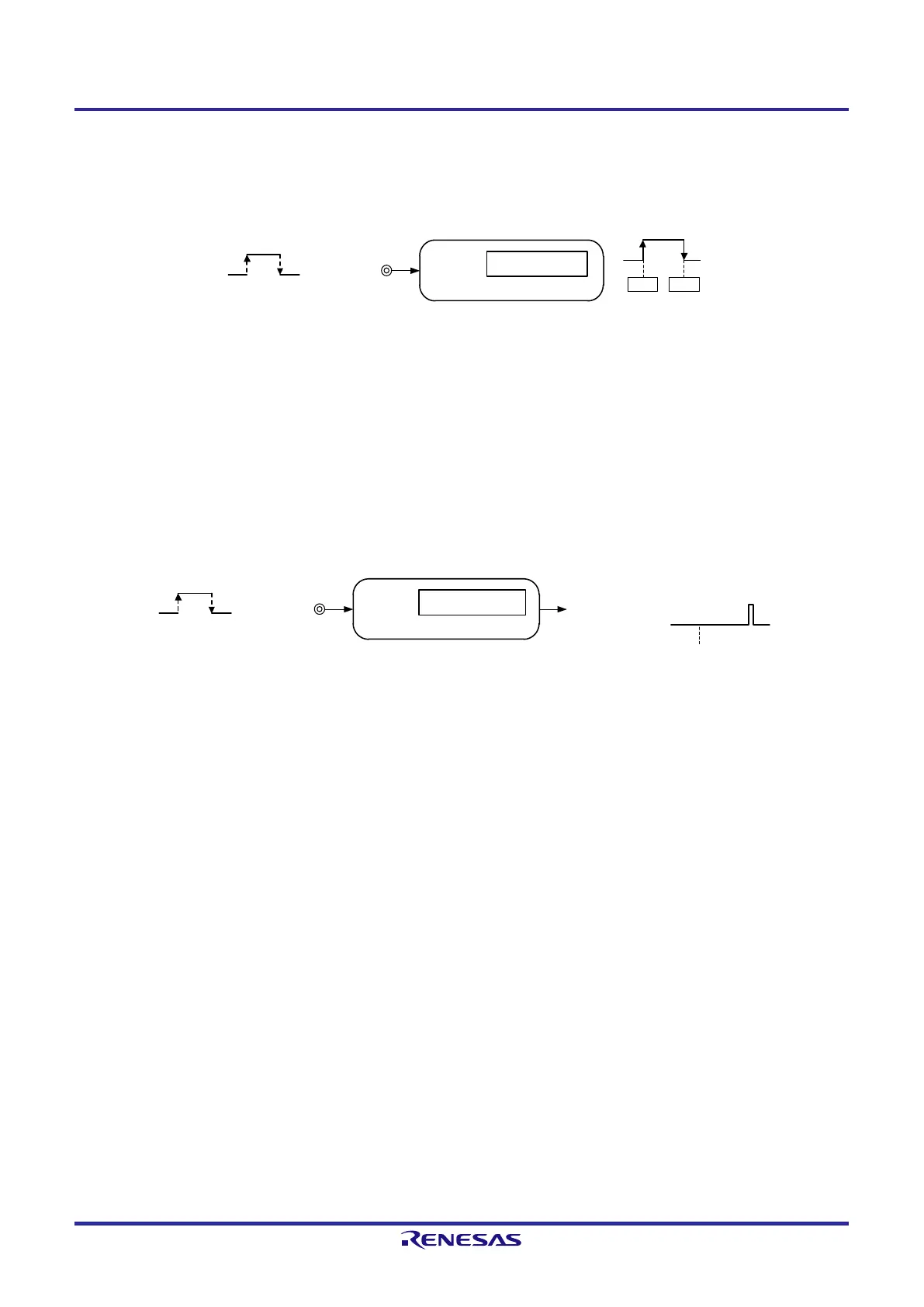
6) Measurement of high-/low-level width of input signal
Counting is started by a single edge of the signal input to the timer input pin (TImn), and the count value is captured at
the other edge. In this way, the high-level or low-level width of the input signal can be measured.
Channel n
Capture operation
Timer input
(TImn
)
Edge detection
Capture
Start
00H
xxH
Remark 1. m: Unit number (m = 0), n: Channel number (n = 0 to 7)
Remark 2. The presence or absence of timer I/O pins of channel 0 to 7 depends on the product. See Table 6-2
Timer I/O Pins provided in Each Product for details.
7) Delay counter
Counting is started at the valid edge of the signal input to the timer input pin (TImn), and an interrupt is generated after
any delay period.
Channel n
Interrupt signal
(INTTMmn)
Compare operation
Timer input
(TImn)
Edge detection
Start
Remark 1. m: Unit number (m = 0), n: Channel number (n = 0 to 7)
Remark 2. The presence or absence of timer I/O pins of channel 0 to 7 depends on the product. See Table 6-2
Timer I/O Pins provided in Each Product for details.
 Loading...


