RL78/G15 CHAPTER 6 TIMER ARRAY UNIT
R01UH0959EJ0110 Rev.1.10 Page 182 of 765
Mar 7, 2023
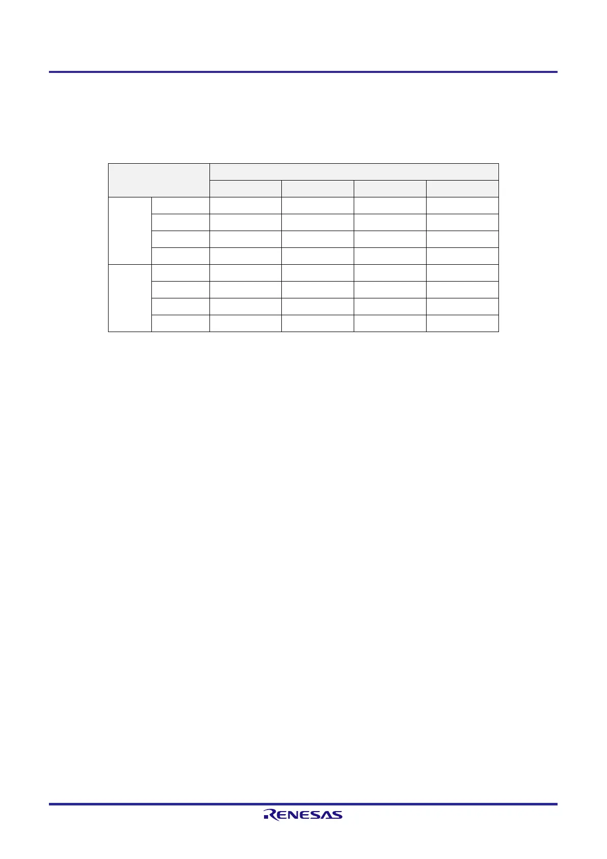
By using channels 1 and 3 in the 8-bit timer mode and specifying CKm2 or CKm3 as the operation clock, the interval
times shown in Table 6-4 can be achieved by using the interval timer function.
Table 6-4. Interval Times Available for Operation clock CKSm2 or CKSm3
Clock Interval time
Note 1
(f
CLK
= 16 MHz)
10 µs 100 µs 1 ms 10 ms
CKm2 f
CLK
/2 — — —
f
CLK
/2
2
— — —
f
CLK
/2
4
— —
f
CLK
/2
6
— —
CKm3 f
CLK
/2
8
— —
f
CLK
/2
10
— —
f
CLK
/2
12
— —
f
CLK
/2
14
— — —
Note 1. The margin is within 5%.
Remark 1. f
CLK
: CPU/peripheral hardware clock frequency
Remark 2. For details of a signal of f
CLK
/2
j
selected with the TPSm register, see 6.5.1 Count clock (fTCLK).
 Loading...


