RL78/G15 CHAPTER 6 TIMER ARRAY UNIT
R01UH0959EJ0110 Rev.1.10 Page 212 of 765
Mar 7, 2023
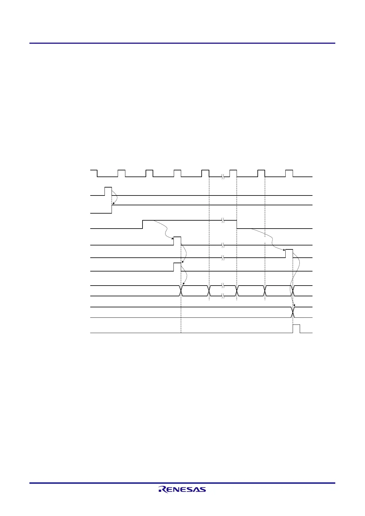
(5) Operation of capture & one-count mode (high-level width measurement)
<1> Operation is enabled (TEmn = 1) by writing 1 to the TSmn bit of timer channel start register m (TSm).
<2> Timer count register mn (TCRmn) holds the initial value until start trigger generation.
<3> Rising edge of the TImn input is detected.
<4> On start trigger detection, the value of 0000H is loaded to the TCRmn register and count starts.
<5> On detection of the falling edge of the TImn input, the value of the TCRmn register is captured to timer data
register mn (TDRmn) and an INTTMmn interrupt is generated.
Figure 6-28. Operation Timing (In Capture & One-count Mode: High-level Width Measurement)
TSmn (Write)
TEmn
Start trigger
detection signal
TCRmn
INTTMmn
<4>
<3>
TImn input
Rising edge
f
MCK
(f
TCLK
)
<1>
Edge detection
<5>
m
Initial value
m + 1
m – 10000
m0000
Falling edge
TDRmn
<2>
Edge detection
Remark Figure 6-28 shows the timing when the noise filter is not used. By making the noise filter on-state, the edge
detection becomes 2 f
MCK
cycles (it sums up to 3 to 4 cycles) later than the normal cycle of TImn input. The
error per one period occurs be the asynchronous between the period of the TImn input and that of the count
clock (f
MCK
).
 Loading...


