RL78/G15 CHAPTER 6 TIMER ARRAY UNIT
R01UH0959EJ0110 Rev.1.10 Page 263 of 765
Mar 7, 2023
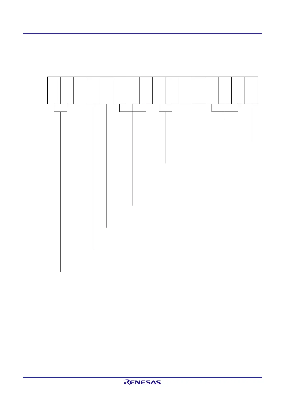
Figure 6-66. Example of Set Contents of Registers When One-Shot Pulse Output Function Is Used
(Master Channel) (1/2)
(a) Timer mode register mn (TMRmn)
15 14 13 12 11 10 9 8 7 6 5 4 3 2 1 0
TMRmn
CKSm
n1
CKSm
n0
CCSm
n
MAST
ERmn
Note 1
2
1
0
CISmn
1
CISmn
0
MDmn
3
MDmn
2
MDmn
1
MDmn
0
1/0 0 0 0 1 0 0 1 1/0 1/0 0 0 1 0 0 0
Operation mode of channel n
100B: One-count mode
Start trigger during operation
0: Trigger input is invalid.
Selection of TImn pin input edge
00B: Detects falling edge.
01B: Detects rising edge.
10B: Detects both edges.
11B: Setting prohibited
Start trigger selection
001B: Selects the TImn pin input valid edge.
Setting of MASTERmn bit (channels 2, 4, 6)
1: Master channel.
Count clock selection
0: Selects operation clock (f
MCK
).
Operation clock (f
MCK
) selection
00B: Selects CKm0 as operation clock of channel n.
10B: Selects CKm1 as operation clock of channel n.
Note 1. TMRm2, TMRm4, TMRm6: MASTERmn = 1
TMRm0: Fixed to 0
Remark m: Unit number (m = 0), n: Master channel number (n = 0, 2, 4, 6)
 Loading...


