RL78/G15 CHAPTER 6 TIMER ARRAY UNIT
R01UH0959EJ0110 Rev.1.10 Page 265 of 765
Mar 7, 2023
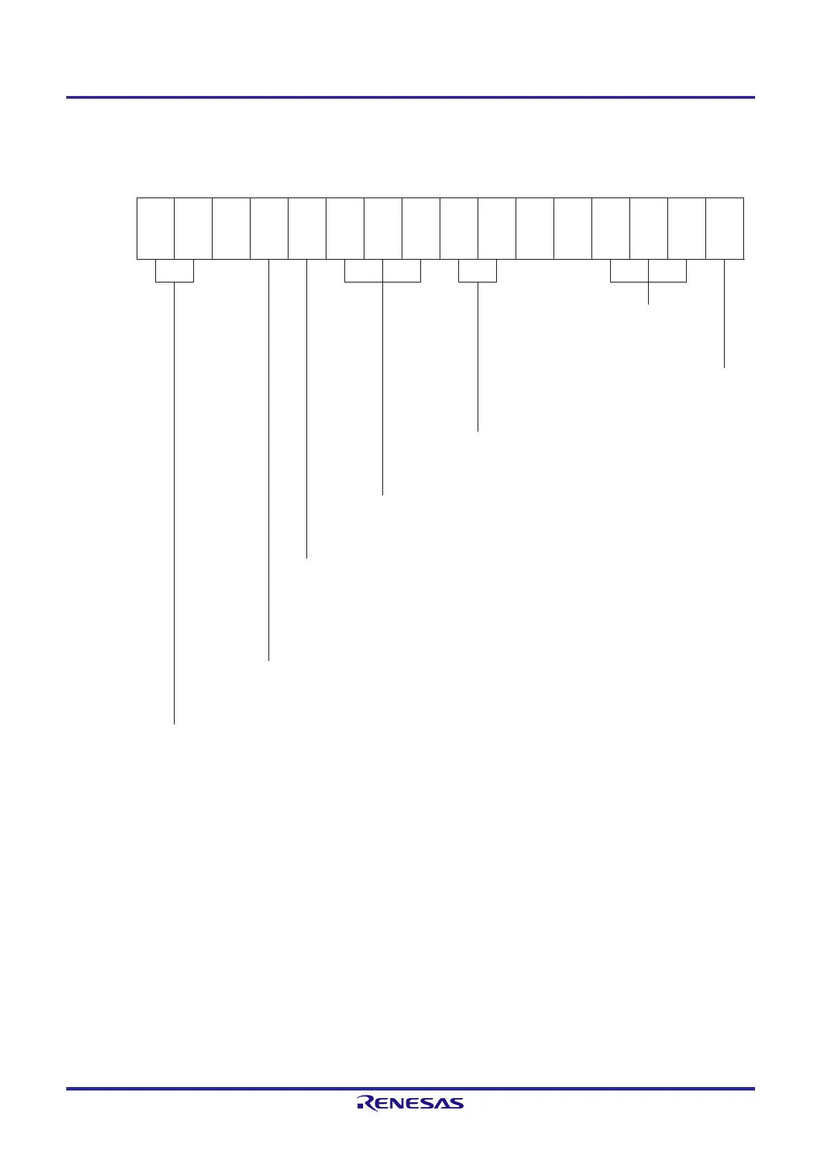
Figure 6-67. xample of Set Contents of Registers When One-Shot Pulse Output Function Is Used (Slave Channel) (1/2)
(a) Timer mode register mp (TMRmp)
15 14 13 12 11 10 9 8 7 6 5 4 3 2 1 0
TMRmp
CKSm
p1
CKSm
p0
CCSm
p
M/S
Note 1
2
1
0
CISmp
1
CISmp
0
MDmp
3
MDmp
2
MDmp
1
MDmp
0
1/0 0 0 0 0 1 0 0 0 0 0 0 1 0 0 0
Operation mode of channel p
100B: One-count mode
Start trigger during operation
0: Trigger input is invalid.
Selection of TImp pin input edge
00B: Sets 00B because these are not used.
Start trigger selection
100B: Selects INTTMmn of master channel.
Setting of MASTERmp bit (channels 2, 4, 6)
0: Slave channel
Setting of SPLITmp bit (channels 1, 3)
0: 16-bit timer mode
Count clock selection
0: Selects operation clock (f
MCK
).
Operation clock (f
MCK
) selection
00B: Selects CKm0 as operation clock of channel p.
10B: Selects CKm1 as operation clock of channel p.
* Make the same setting as master channel.
Note 1. TMRm2, TMRm4, TMRm6: MASTERmn bit
TMRm1, TMRm3: SPLITmp bit
TMRm5, TMRm7: Fixed to 0
Remark m: Unit number (m = 0), n: Master channel number (n = 0, 2, 4, 6)
p: Slave channel number (n < p ≤ 7)
 Loading...


