RL78/G15 CHAPTER 6 TIMER ARRAY UNIT
R01UH0959EJ0110 Rev.1.10 Page 295 of 765
Mar 7, 2023
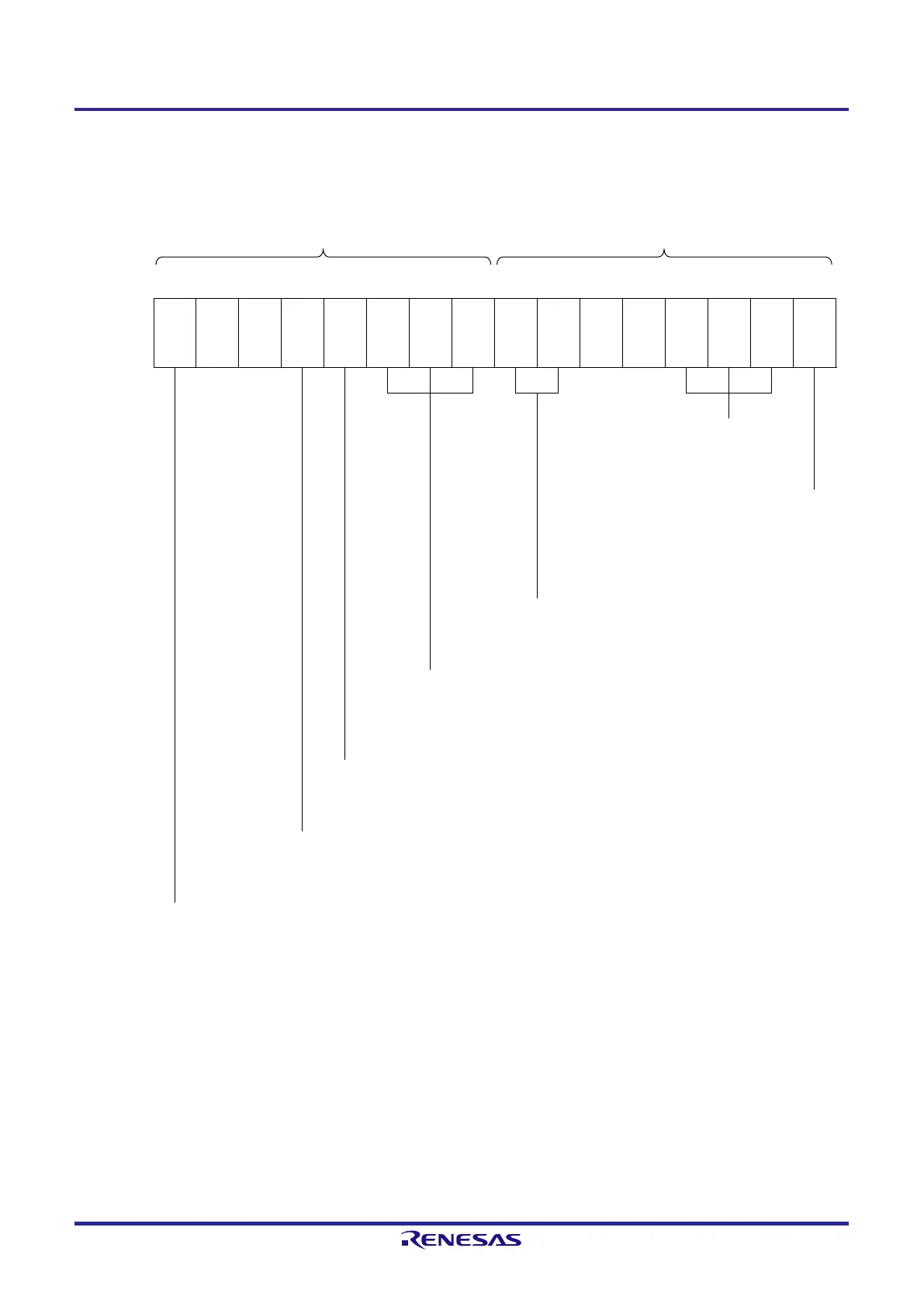
Figure 6-82. Example of Set Contents of Registers for Two-channel Input with One-shot Pulse Output Function
(Slave Channel) (1/2)
(a) Timer mode register 0p (TMR0pH, TMR0pL)
TMR0pH TMR0pL
7 6 5 4 3 2 1 0 7 6 5 4 3 2 1 0
TMR0p
CKS0p
1
S
STS0p
2
STS0p
1
STS0p
0
1/0 0 0 0 0 1 1 0 0 0 0 0 0 1 0 0
Operation mode of channel p
010B: Capture mode
Setting of operation when
counting is started
0: Does not generate INTTM0p
when counting is started.
Selection of TI0p pin input edge
00B: Detects falling edge.
Trigger selection
110B: Selects INTTM0n of master channel as the start trigger and selects TI0p pin
input valid edge of slave channel as the end trigger (capture trigger).
Setting of SPLIT0p bit (Channel 3)
0: 16-bit timer mode
Count clock selection
0: Selects operation clock (f
MCK
).
Operation clock (f
MCK
) selection
0: Selects CK00 as operation clock of channel p.
1: Selects CK01 as operation clock of channel p.
* Make the same setting as master channel.
Remark n: Master channel number (n = 0, 2)
p: Slave channel number (p = 3)
 Loading...


