RL78/G15 CHAPTER 12 SERIAL ARRAY UNIT
R01UH0959EJ0110 Rev.1.10 Page 472 of 765
Mar 7, 2023
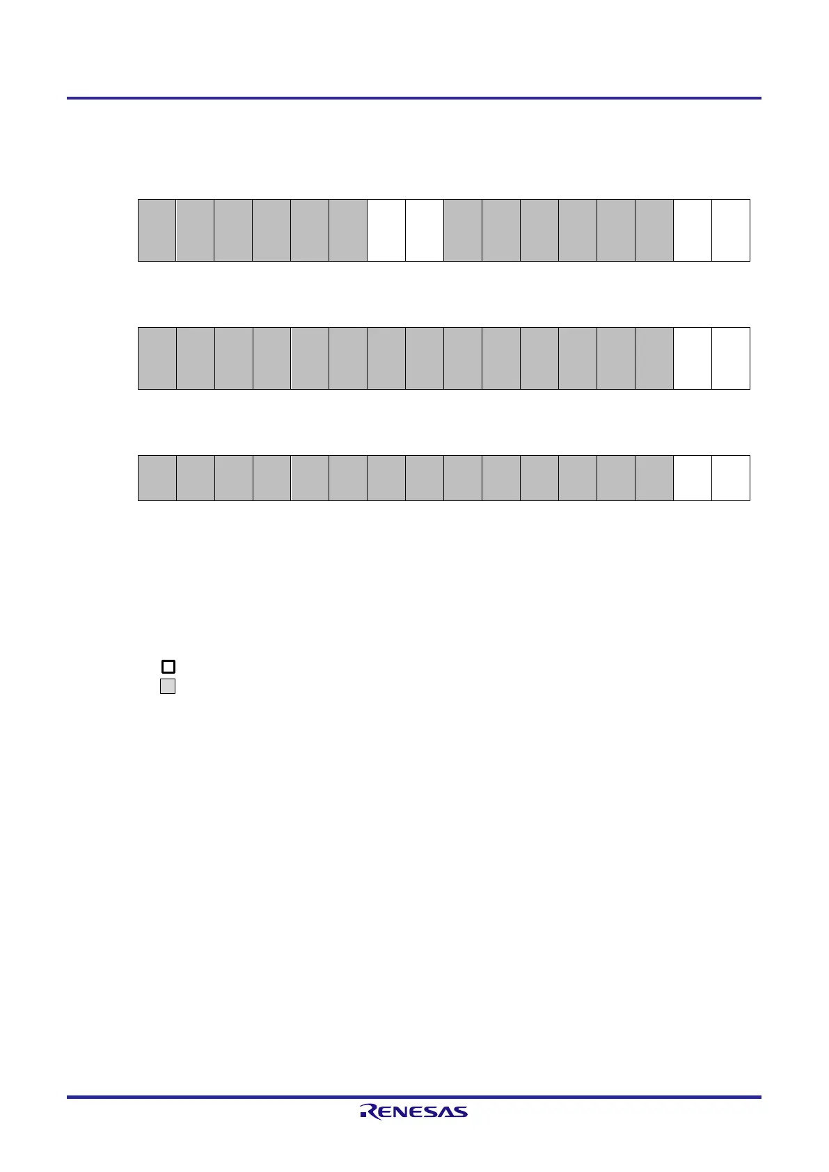
Figure 12-76. Example of Contents of Registers for UART Reception of UART (UART0) (2/2)
(e) Serial output register m (SOm) … This register is not used in this mode.
15 14 13 12 11 10 9 8 7 6 5 4 3 2 1 0
SOm
CKOm
1
CKOm
0
SOm1
SOm0
0 0 0 0 0 0 × × 0 0 0 0 0 0 × ×
(f) Serial output enable register m (SOEm) … This register is not used in this mode.
15 14 13 12 11 10 9 8 7 6 5 4 3 2 1 0
SOEm
SOEm
1
SOEm
0
0 0 0 0 0 0 0 0 0 0 0 0 0 0 × ×
(g) Serial channel start register m (SSm) … Set only the bit of the target channel to 1.
15 14 13 12 11 10 9 8 7 6 5 4 3 2 1 0
SSm
SSm1
SSm0
0 0 0 0 0 0 0 0 0 0 0 0 0 0 0/1 ×
Note 1. When UART performs 9-bit communication, bits 0 to 8 of the SDRm0 register are used as the reception data
specification area.
Caution For the UART reception, be sure to set the SMRmr register of channel r to UART transmission mode
that is to be paired with channel n.
Remark 1. m: Unit number (m = 0), n: Channel number (n = 1), r: Channel number (r = n – 1),
q: UART number (q = 0), mn = 01
Remark 2.
: Setting is fixed in the UART reception mode,
: Setting disabled (set to the initial value)
×: Bit that cannot be used in this mode (set to the initial value when not used in any mode)
0/1: Set to 0 or 1 depending on the usage of the user.
 Loading...


