15 February 2006 PUNCH UNIT (B377)
1-43
Installation
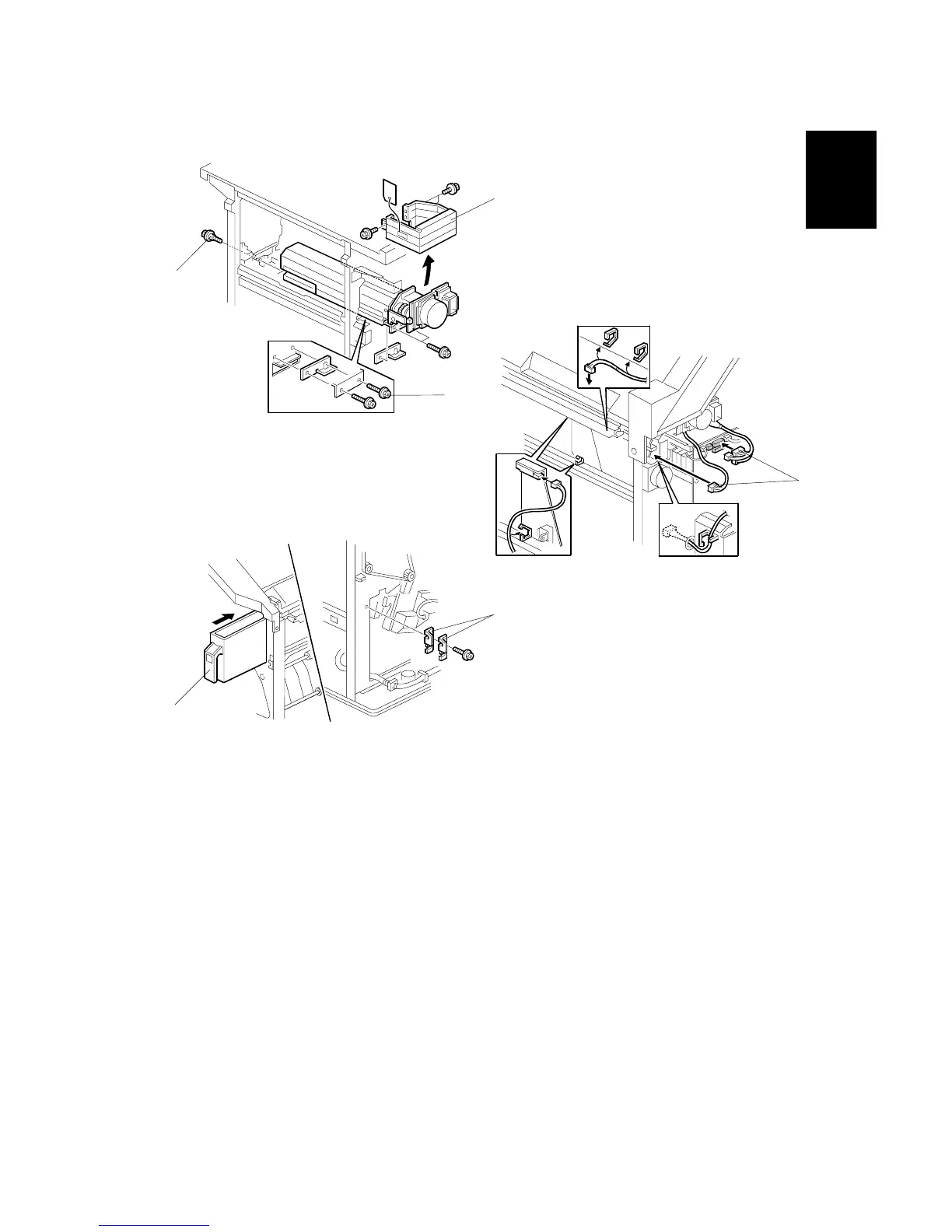
8. Remove the shipping bracket [A] (" x 2).
9. Position the 2 mm spacer [B] and secure the punch unit (" x 2).
10. Secure the punch unit at the front with the shoulder screw [C] (" x 1).
11. Connect the harnesses [D] and clamp them as shown.
NOTE: No special DIP switch settings are required for this punch unit. The
punch unit sends an identification signal to the machine, so it knows
what type of punch unit has been installed.
12. Slide the hopper [E] into the machine.
13. Fasten the two 1 mm spacers [F] to the rear frame. These may be used during
future adjustments.
NOTE: The spacers are used to adjust the horizontal positioning of the holes.
14. Reassemble the finisher and check the punch operation.
B377I203.WMF
B377I106.WMF
B377I105.WMF
[B]
[C]
[A]
[E]
[F]
[D]