OnAir Digital Mixing Consoles
Conguration 6-91
Document generated: 10.10.14
SW V6.0
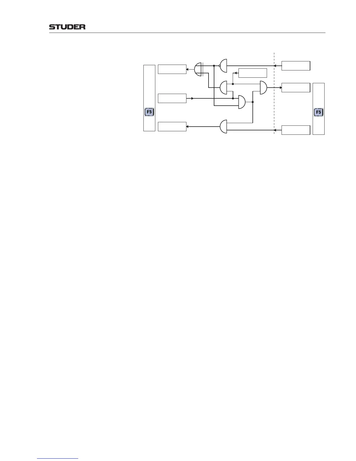
OnAir 3000 (C1) OnAir 2500 (C2)
GPInputFunction 11
UserLED5
XOR
1
1
2
1
2
1
2
1
2
1
2
AND
1
AND
2
AND
3
AND
4
NOT
1
GPOutputFunction 11
UserKey5
Flashing: Call Initiated
Bright: Call Enabled
Dark: Call Disabled
Flashing:
Caller Indication
GPInputFunction 17
UserKey5
GPOutputFunction 1
Generator
GPOutputFunction 16
RedLight OnAir
GPInputFunction 5
UserLED5
GPOutputFunction 5
UserKey5
F5
F5
1
st
Case Let’s assume that C2 is off-air for a start (i.e., GPOutputFunction 16 of C2
is low). The F5 user key on C2 is dark. The F5 user key on C1 is illuminated,
indicating that a call signal from C1 to C2 is allowed.
• TheC1operatorpresseshisF5 key; GPOutputFunction 11 and input 1 of
AND2 go high. The output of AND2 goes high, too
• TheoutputofAND3alternateswith the rate of GPOutputFunction1
(generator), and the GPInputFunction 5 of C2 makes the C2 F5 key
(UserLED5) flash.
• TheoutputofAND1alternatestooandmakestheF5 key on C1 (UserLED5)
flash via XOR1.
• OperatorC2confirmsthecallsignalbypressinghisflashingF5 key. Input
2 of AND4 goes high. Since input 1 of AND4 (output of AND2) is high as
well, the output of AND4 goes high and turns, via the GPInputFunction
17, the GPOutputFunction 11 off again.
2
nd
Case If C2 is on-air (i.e., GPOutputFunction 16 of C2 is high), the C1 F5 key is
dark.
• TheC1operatorpresseshisF5 key; GPOutputFunction 11 and input 1 of
AND2 go high.
• Sinceinput2ofAND2islow(outputofNOT1islow),theouptutofAND3
remains low and the F5 key on C2 remains dark; the C2 operator is not
disturbed.
• TheoutputofAND1stillalternatesandmakestheF5 key on C1 flash,
telling the C1 operator that his call has been sent out.
• AssoonasC2goesoff-air,theoutputofNOT1changesfromlowtohigh,
opening the call signal path to C2; the F5 key on C2 flashes.
• OperatorC2confirmsthecallsignalbypressinghisflashingF5 key. Input
2 of AND4 goes high. Since input 1 of AND4 (output of AND2) is high as
well, the output of AND4 goes high and turns, via the GPInputFunction
17, the GPOutputFunction 11 off again.
Notes As can easily be seen from the diagram above, the whole logic is implemented
in console C1. This is not mandatory, but allows implementing custom logic
in a system that also incorporates OnAir 2500 consoles without a memory
upgrade.
Configuration Procedure Although the logic diagram is not very complicated, a structured procedure
is recommended. Implementing the desired functionality is much easier if a
diagram is available where also the gate inputs are numbered.
First of all, since no hardware GPIOs are used, neither GPInputs nor GPOut-
puts need to be configured in our case – all that needs to be done takes place
in the GPIOFunctions and CustomLogic sections of the configuration tool.
 Loading...


