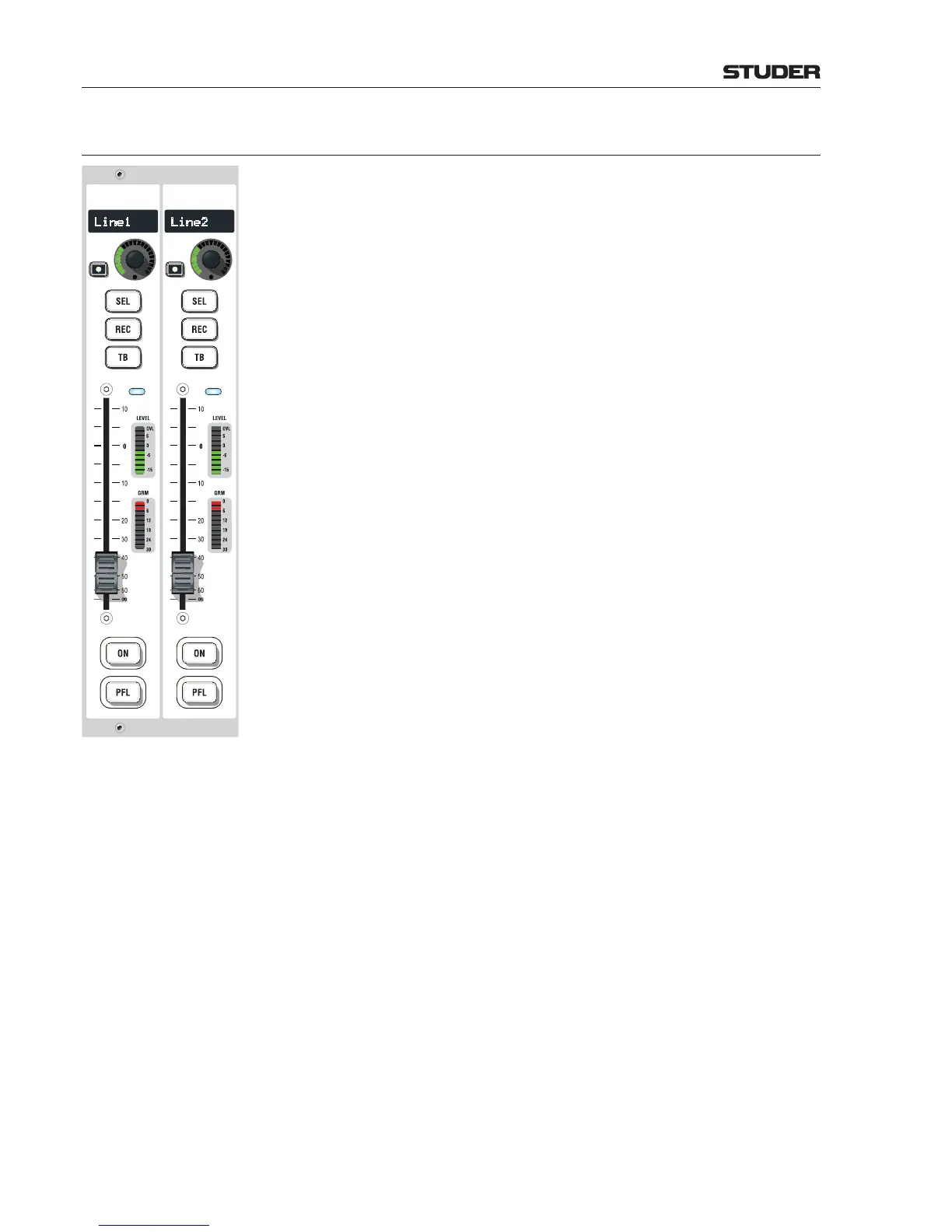
The LED fader module contains three or six fader strips (only two of them
shown in the illustration on the left; approx. 50% original size). Up to eight
fader modules can be combined, giving the maximum configuration for a
48-fader desk.
Every fader strip contains five large, configurable keys, the fader, an LED
input level meter with overload indication, an LED gain reduction meter, a
rotary encoder with LED ring and associated key, an eight-digit alphanumeric
channel label display, and a blue channel-active indicator (illuminated if chan-
nel is ON, fader is open, channel is assigned to a main output, and master
fader is open. Since SW V5.0 it is also illuminated if a subgroup is used as a
summing bus on a journalist desk).
The channel strip has been designed with as few operating elements as pos-
sible. However, all other functions are ava ilable through the rotary modules,
the configurable user keys, or on the main screen. Similar to the OnAir 2000,
fader touch screen modules can be attached above the fader modules to main-
tain fast system overview and direct access to the most used functions.
Symbols on the screens show the current settings for every channel. Touching
one of the symbols assigns the main screen to this function. Parameters can
now be entered by rotary encoders (e.g. EQ parameters) or directly by the
corresponding touch screen buttons (e.g. EQ on/off). The new settings are
immediately visible on the channel screen.
All keys can be freely configured and assigned, and the large fader module
keys have transparent snap-on caps for convenient labeling. This allows for
example to have ON and OFF keys at the lower end of the channel strip if
required, or to assign a different function to the TB key if the source is e.g.
a CD player. These settings are input source-related and will automatically
follow the source in case the routing is changed.
ON Pressing the ON key toggles the channel on/off function. In the audio path,
the on/off switch is located after fader and panning. ‘On’ status is indicated
by illuminating the key.
The function is disabled when the corresponding fader is configured as master
fader for a certain bus.
PFL The purpose of PFL is to feed the pre-fader audio signal of the desired channel
orAUXsend,group,ormaster(program,record)tothePFLbus.Ifactive,
the key is illuminated in yellow.
If the ‘PFL Cut on Channel Active’ function (also referred to as ‘broadcast
PFL mode’) is enabled, audio signals are temporarily cut from the PFL bus
as long as the channel is ON and the fader is open. In such a case the PFL key
is illuminated in amber.
If the module is configured as extended desk, the PFL audio signal is fed to
the PFL Studio1 bus.
Please note that this key can also be configured as CUE key. The purpose of
CUE is to feed the after-fader, after-pan and pre-ON audio signal of the desired
channelorAUXsend,group,ormaster(program,record)tothePFLbus.If
active, the key is illuminated in yellow.