OnAir 3000 Digital Mixing Console
Operation 5-113
Document generated: 10.10.14
SW V6.0
by the RCS for identifying a router output) to the logical inputs to which the
router outputs are connected. The destination IDs are used to set crosspoints
when the user selects a source in the CHAN - Input page (see below), and
when the RCS reports labels. The default assignment is 1:1, i.e., logical input
1 is destination ID 1.
Examples:
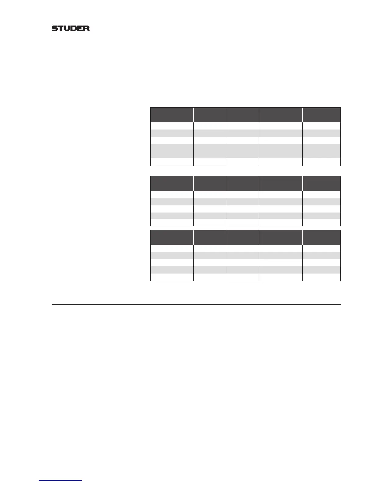
Single C-Desk for Sports Program
Input Signal MADI In MADI Out Output Signal
Router
Destination ID
Ext. Line 1 - 12 1 - 24 1 - 24 Ret. Line 1 - 12 00 - 11
Ext. Inp. 1 - 8 33 - 48 16 - 23
Monitoring 49 - 64
33 - 38
PRG A, PRG B,
REC
39 - 46 AUX 1 - 4
A/B Desk
- Primary Desk (B)
Input Signal MADI In MADI Out Output Signal
Router
Destination ID
Ext. Line 1 - 12 1 - 16 1 - 16 Ret. Line 1 - 8 00 - 07
Ext. Inp. 1 - 8 17 - 32 16 - 23
Monitoring 33 - 48
19 - 22 PRG B, REC
25 - 30 AUX 2, 4
- Secondary Desk (C)
Input Signal MADI In MADI Out Output Signal
Router
Destination ID
Ext. Line 1 - 12 51 - 54 51 - 54 Ret. Line 1 - 2 24, 25
Ext. Inp. 1 - 8 55 - 58 40, 41
Monitoring 33 - 48
17, 18 PRG A
23, 24 AUX 1
5.8.8.1 Operation
External Line Selection Input selection (see chapter 5.3.2.1) has been extended for this purpose; exter-
nal lines (four-wire connections, i.e. logical inputs controlling an N–X) and
external inputs (two-wire connections, logical inputs without N–X control)
from the central router have been added to the grouping of internal sources
(MIC, LINE, AES/EBU, ADAT, etc.) in the input selection dialog.
External line 1 - 8 opens a list of external four-wire lines from/to a codec
for selection. External input 1 - 8 allows selecting the input signals without
return lines, but from the same codecs.