OnAir 3000 Digital Mixing Console
Operating Elements 4-17
Document generated: 10.10.14
SW V6.0
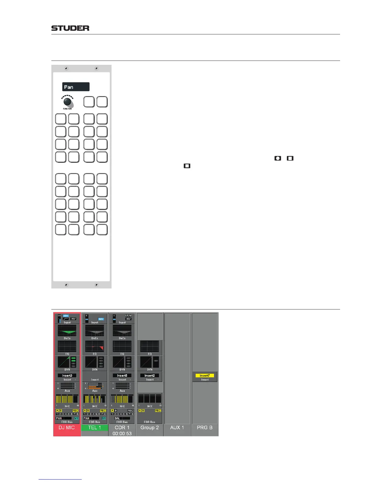
4.5 Fader Assign Module
Pan
PAN/
BAL
GAIN/
CAL
INP.
ROUT
N–X
SUM
RESET
PFL
EXT
PFL 1
AUX 1 AUX 2 AUX 3 AUX 4
N–X
BUS 1
N–X
BUS 2
N–X
BUS 3
N–X
BUS 4
PGM A
ASSIGN
PGM B
ASSIGN
REC
ASSIGN
.
METER
PF
F 1 SNAP 1 SNAP 5
METER
AF
F 2 SNAP 2 SNAP 6
METER
N–X
F 3 SNAP 3 SNAP 7
GRM
C/L
F 4 SNAP 4 SNAP 8
GRM
DEES
F 5 ENABLE SNAP 9
This module allows assigning a function to the rotaries in the fader module,
using its own rotary encoder. Turning the rotary shows a sequence of the
available functions (e.g. gain, pan/balance, input source) in the display next
to the rotary. Alternatively, the desired rotary functions in the fader modules
can also be assigned to dedicated keys, making them accessible in an even
faster way.
The module consists of two functional key blocks in a default setting. All
keys are freely configurable and have transparent snap-on caps for convenient
labeling. The functions most used in the desired application can be assigned
to the keys.
The upper key block contains a number of keys for quick access to the dif-
ferent functions assignable to the rotary and the
/ keys on the fader
modules (the key is supported by the OLED version only).
In the lower key block there is an array of keys without dedicated functions
that can be used to access GPIOs, machine remote control, etc., according to
the user’s requirements.
Generally speaking, all keys in this array may be used for any console-internal
or, via GPOs, also for any console-external function.
Examples for console-internal functions:
• Snapshotrecall
• Routingrecall
• Faderchannelmetermode(AF,PF,N–Xlevel),etc.
Examples for console-external functions:
• Red/greenlightcontrol
• Tapemachineremotecontrol(STOP,PLAY,REC,<<,>>)
• Doorcontrol
• Ringtone,etc.
4.6 Channel Screen
The OnAir 3000 features optional 12” color
channel touch screens for ‘Touch’n’Action’
operation. The channel screens are subdi-
vided in 6 rows above each fader strip of the
fader module and include symbols for the
most important channel settings. The sym-
bols display qualitative and quantitative real-
time information. This means that they are
not just symbols but a true reproduction of,
for example, the currently set EQ curve.
Parameters currently not active are displayed
in gray but with the correct information;
parameters currently active are displayed in
their respective color (such as blue for input,
red for EQ, green for dynamics/de-esser,
orangeforAUX, yellowforN–Xandbus
assignment). At the lower end the source
label is displayed.