03/01
6-6
Phaser 790/DocuColor 2006
GP 2
General Procedures and Information
NOTE: In the digital output test mode, each component is actuated using the DO TEST menu
and deactuated using the STOP DO TEST menu. Therefore, to deactuate an actuated compo-
nent, you must first go back to the STOP DO TEST menu and select the component again. If
multiple codes are stacked, components should be deactivated in the sequence in which they
were switched on.
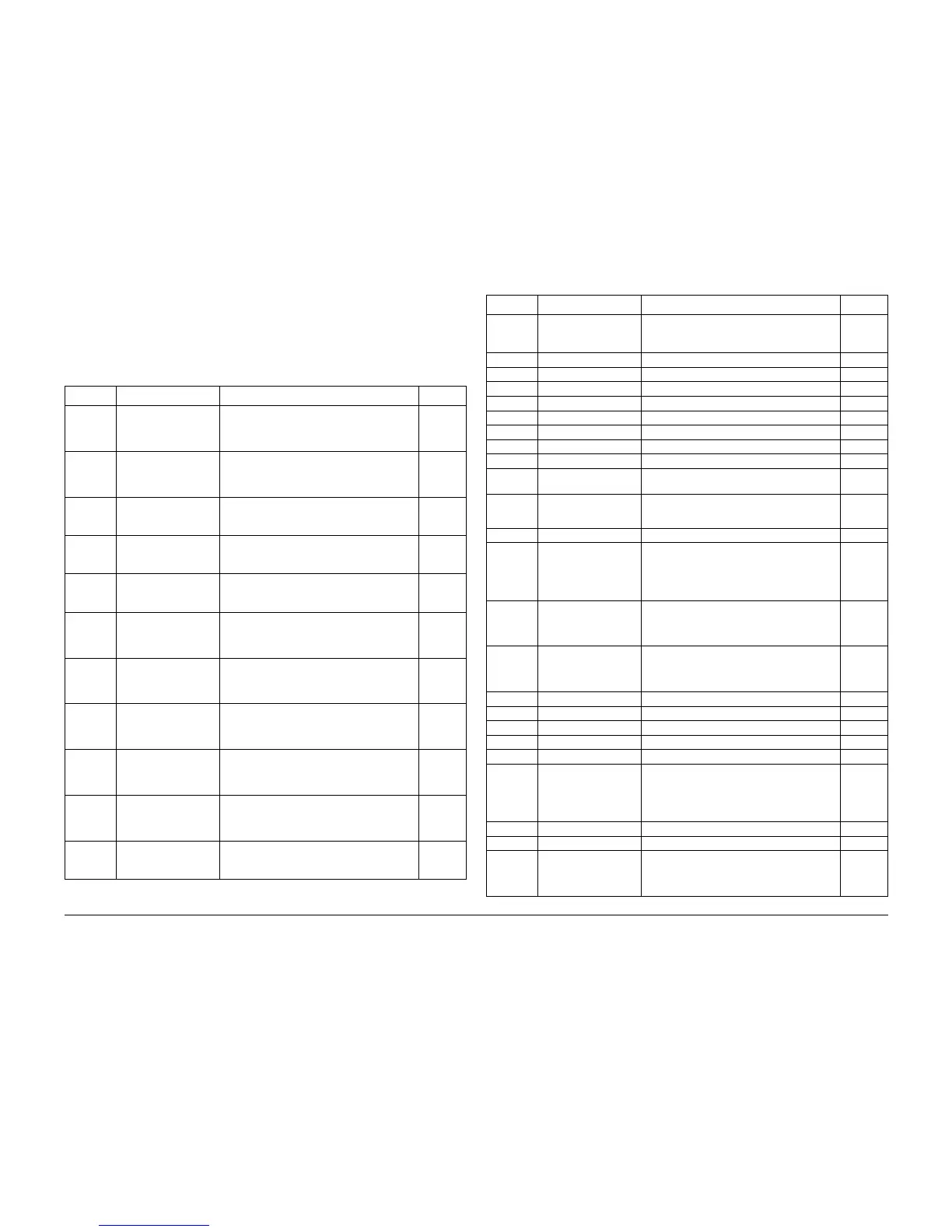
The following table lists the digital output codes.
Table 3 Digital Output Codes
DO Code Component Signal BSD Ref
00 Process Drive Unit NOTE: see WARNINGS and CAUTIONS
Process Motor Speed 0 (half-speed)
Stack with DO code 54
9.2
06 Process Drive Unit NOTE: see WARNINGS and CAUTIONS
Process Motor Speed 1 (1/3rd speed)
Stack with DO code 54
9.2
07 Optional Feeder Start Signal
Check signal state with DMM (refer to BSD
3.4 for connection)
3.4
08 Optional Feeder Start Signal
Check signal state with DMM (refer to BSD
3.4 for connection)
3.4
09 Duplex Option Start Signal
Check signal state with DMM (refer to BSD
3.5 for connection)
3.5
0A HVPS NOTE: see WARNINGS and CAUTIONS.
Function not currently supported
BTR 2 Bias On (L) +24 VDC
9.7
0B HVPS NOTE: see WARNINGS and CAUTIONS.
Function not currently supported
BTR 1 Bias On (L) +24 VDC
9.6
0C HVPS NOTE: see WARNINGS and CAUTIONS.
Function not currently supported
Developer DC Bias On (L) +24 VDC
9.4
0D HVPS NOTE: see WARNINGS and CAUTIONS.
Function not currently supported
Developer AC Bias On (L) +24 VDC
9.4
0E HVPS NOTE: see WARNINGS and CAUTIONS.
Function not currently supported
BCR DC On (L) +24 VDC
9.1
10 Rotary Motor Rotary Motor Low Speed On (L) +5 VDC
Check signal state with DMM (refer to BSD
9.3 for connection)
9.3
11 Rotary Motor Rotary Motor On (L) +5 VDC
Check signal state with DMM (refer to BSD
9.3 for connection)
9.3
17 Exchange Solenoid Exchange Solenoid Push (L) +24 VDC 10.4
18 Exchange Solenoid Exchange Solenoid Pull (L) +24 VDC 10.4
19 Inverter Solenoid Inverter Solenoid Push (L) +24 VDC 10.5
1A Inverter Solenoid Inverter Solenoid Pull (L) +24 VDC 10.5
1B Feed Solenoid Feed Solenoid On (L) +24 VDC 8.1
1C Turn Clutch Turn Clutch On (L) +24 VDC 8.1
1E Registration Clutch Registration Clutch On (L) +24 VDC 8.7
1F Preregistration Clutch Preregistration Clutch On (L) +24 VDC 8.7
20 Bypass Tray Feed
Clutch
Feed Clutch On (L) +24 VDC 8.2
21 Developer Clutch NOTE: see WARNINGS and CAUTIONS
Developer Clutch On (L) +24 VDC
9.4
22 MCU PWB Not used --
23 Lift Motor NOTE: see WARNINGS and CAUTIONS
Requires input of a directional code (DO-2D
or DO-2E) to activate.
Limited duration (.12 sec)
7.2
2D Lift Motor NOTE: see WARNINGS and CAUTIONS
Requires stacking with DO-23 to activate.
Limited duration (.12 sec)
7.2
2E Lift Motor NOTE: see WARNINGS and CAUTIONS
Requires stacking with DO-23 to activate.
Limited duration (.12 sec)
7.2
3A MCU PWB Function not currently supported --
3C MCU PWB Function not currently supported --
3F MCU PWB Function not currently supported --
44 ROS Function not currently supported --
46 MCU PWB Function not currently supported --
47 Heat Roll Heat Lamp,
Pressure Roll Heat
Lamp
NOTE: see WARNINGS and CAUTIONS
Heat Roll Heat Lamp, Pressure Roll Heat
Lamp On (L) +5 VDC
Limited duration (.12 sec)
10.2
4C MCU PWB Function not currently supported --
52 Paper Handling Motor Function not currently supported --
53 Fuser Motor, Paper
Handling Motor
NOTE: see WARNINGS and CAUTIONS
Motor On (L) +5 VDC (full speed unless
stacked with code DO-57 or DO-62)
4.1
Table 3 Digital Output Codes
DO Code Component Signal BSD Ref