12.5 d: References
732 YASKAWA SIEPC71061705H GA700 Series Technical Manual
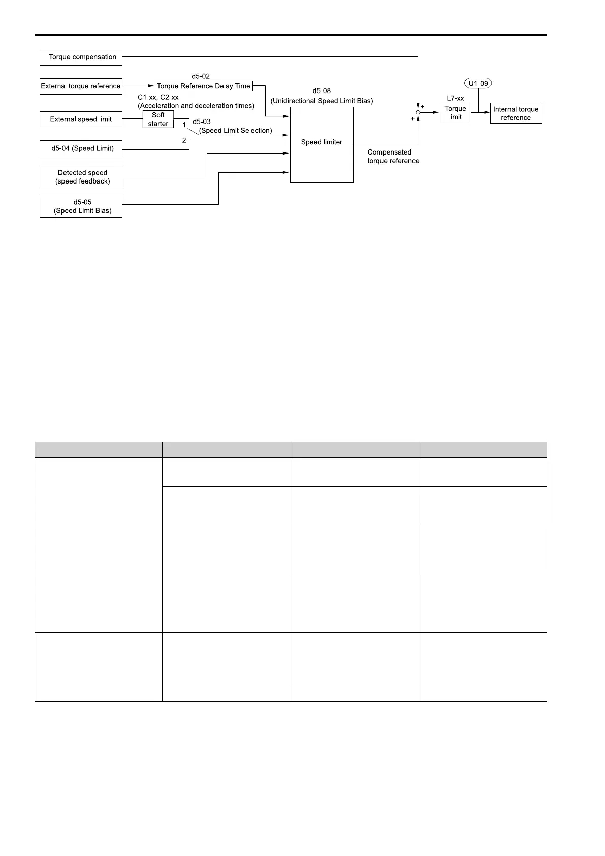
Figure 12.72 Torque Control Block Diagram
The externally input torque reference is the target value for the motor output torque. If the motor output torque
and load torque are not balanced during Torque Control, the motor accelerates or decelerates. To prevent operation
beyond the speed limit, the drive corrects the external torque reference if the motor speed reaches the speed limit.
The speed limit, speed feedback, and the speed limit bias are the values that calculate the compensation value.
When an external torque compensation value is input, the drive adds that value to the speed limit compensated
torque reference value. The values L7-01 to L7-04 [Torque Limit] limit the resulting torque reference. The drive
uses the value as the internal torque reference. You can use U1-09 [Torque Reference] to monitor the calculated
torque reference. The torque limit values set in L7-01 to L7-04 are most important. Although you can set a higher
external torque reference from an external source, the motor will not operate a torque output higher than the
values set in L7-01 to L7-04.
■ Setting the Torque Reference, Speed Limit, and Torque Compensation Values
Torque Control Input Value Selection
Table 12.43 lists the method for torque control input signals.
Table 12.43 The Method for Torque Control Input Signals
Configuration Parameter Signal Input Method Parameter Settings Notes
Torque Reference Drive analog input terminals A1, A2, A3 H3-02, H3-10, H3-06 = 13 [MFAI
Function Select= Torque Reference /
Torque Limit]
*1
The level of the set input signal must align
with the polarity of the external signals.
Analog reference option cards AI-A3 • F2-01 = 0 [Analog Input Function
Selection = 3 Independent Channels]
• H3-02, H3-10, and H3-06 = 13
*1
H3-02, H3-10, or H3-06 settings are
enabled for the option card input terminal.
The level of the set input signal must align
with the polarity of the external signals.
MEMOBUS register 0004H • b1-01 = 2 [Frequency Reference
Selection 1 = Memobus/Modbus
Communications]
• When register bit 2 of 000FH = 1, the
torque reference and torque limit from
register 0004H is enabled.
-
Communication option card • b1-01 = 3 [Option PCB]
• F6-06 = 1 [Torque Reference/Limit by
Comm = Enabled]
Refer to the communication option card
manual for more information about the
torque reference setting.
-
Speed Limit Frequency Reference Selection
(Reference source selected with b1-01)
d5-03 = 1 [Speed Limit Selection = Active
Frequency Reference]
The drive gets the speed limit from the
frequency reference source input in b1-01
or b1-15 [Frequency Reference Selection
2].
*1
The drive applies the settings in C1-01 to
C1-08 [Acceleration/Deceleration Times]
and C2-01 to C2-04 [S-Curve Time @
Start/End of Accel/Decel] to the speed
limit.
d5-04 [Speed Limit] d5-03 = 2 [d5-04 Setting]
-

 Loading...


