Parameter Details
12
12.5 d: References
YASKAWA SIEPC71061705H GA700 Series Technical Manual 733
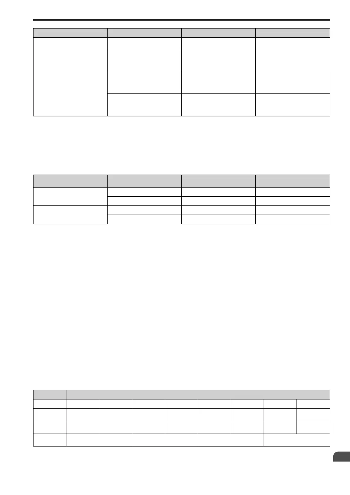
Configuration Parameter Signal Input Method Parameter Settings Notes
Torque Compensation Drive analog input terminals A1, A2, A3 H3-02, H3-10, or H3-06 = 14 [Torque
Compensation]
*1
The level of the set input signal must align
with the polarity of the external signals.
Analog reference option cards AI-A3 • F2-01 = 0
• H3-02, H3-10, or H3-06 = 14
*1
H3-02, H3-10, or H3-06 settings are
enabled for the option card input terminal.
The level of the set input signal must align
with the polarity of the external signals.
MEMOBUS register 0005H • b1-01 = 2
• When register bit 3 of 000FH = 1, the
torque reference and torque limit from
register 0005H is enabled.
-
Communication option card b1-01 = 3
Refer to the communication option card
manual for more information about the
torque reference setting.
-
*1 Sets analog input terminals A1, A2, and A3 to supply the speed limit, torque reference, or torque compensation. If you set the same
function to A1 to A3 terminals with H3-02, H3-10, or H3-06, the drive will detect oPE07 [Analog Input Selection Error].
Input Signal Polarity
The positive and negative torque references set the motor rotation direction. The direction of the Run command
does not set it. The positive and negative torque reference signals and the direction of the Run command have an
effect on the internal torque reference.
Table 12.44 Torque Control Signal Polarity
Run Command Direction Torque Reference Signal Polarity Direction of Motor Rotation
Polarity of the Internal Torque
Reference [U1-09]
Forward run + (Positive) Forward direction + (Positive)
- (Negative) Reverse direction - (Negative)
Reverse run + (Positive) Reverse direction - (Negative)
- (Negative) Forward direction + (Positive)
Note:
For Yaskawa motors, the forward run direction is counterclockwise direction when seen from the load shaft.
When you use analog inputs, you can get negative input values with these methods:
• Apply negative voltage input signals.
• Use positive voltage input signals and set the analog input bias to negative values.
• Apply positive voltage input signals and use a digital input programmed for Analog TorqueRef Polarity Invert
[H1-xx = 78].
When you use MEMOBUS/Modbus communication or a communication option card, set the positive or negative
signed torque reference.
When the level of the analog signal input is 0 V to 10 V or 4 mA to 20 mA, the torque reference is the forward
direction. To reverse the polarity of the torque reference, use one of these two methods:
• Use a -10 V to +10 V voltage input
• Set H1-xx = 78 [MFDI Function Select = Analog TorqueRef Polarity Invert].
■ Speed Limit and Speed Limit Bias
The drive reads the speed limit setting from the input selected in d5-03 [Speed Limit Selection]. You can use d5-
05 [Speed Limit Bias] to add a bias to this speed. Parameter d5-08 [Uni-directional Speed Limit Bias] sets how
the drive applies bias to the speed limit.
Table 12.45 shows the relation between these settings:
Table 12.45 Speed Limit, Speed Bias and Speed Limit Priority Selection
Operating Conditions
Run command Forward Reverse Forward Reverse Forward Reverse Forward Reverse
Torque reference
direction
+ (Positive) + (Positive) - (Negative) - (Negative) - (Negative) - (Negative) + (Positive) + (Positive)
Speed limit
direction
+ (Positive) - (Negative) - (Negative) + (Positive) + (Positive) - (Negative) - (Negative) + (Positive)
Direction of
motor rotation
Forward Reverse Forward Reverse

 Loading...


