8–24 Chapter 8: Configuration and Remote System Upgrades in Cyclone IV Devices
Configuration
Cyclone IV Device Handbook, May 2013 Altera Corporation
Volume 1
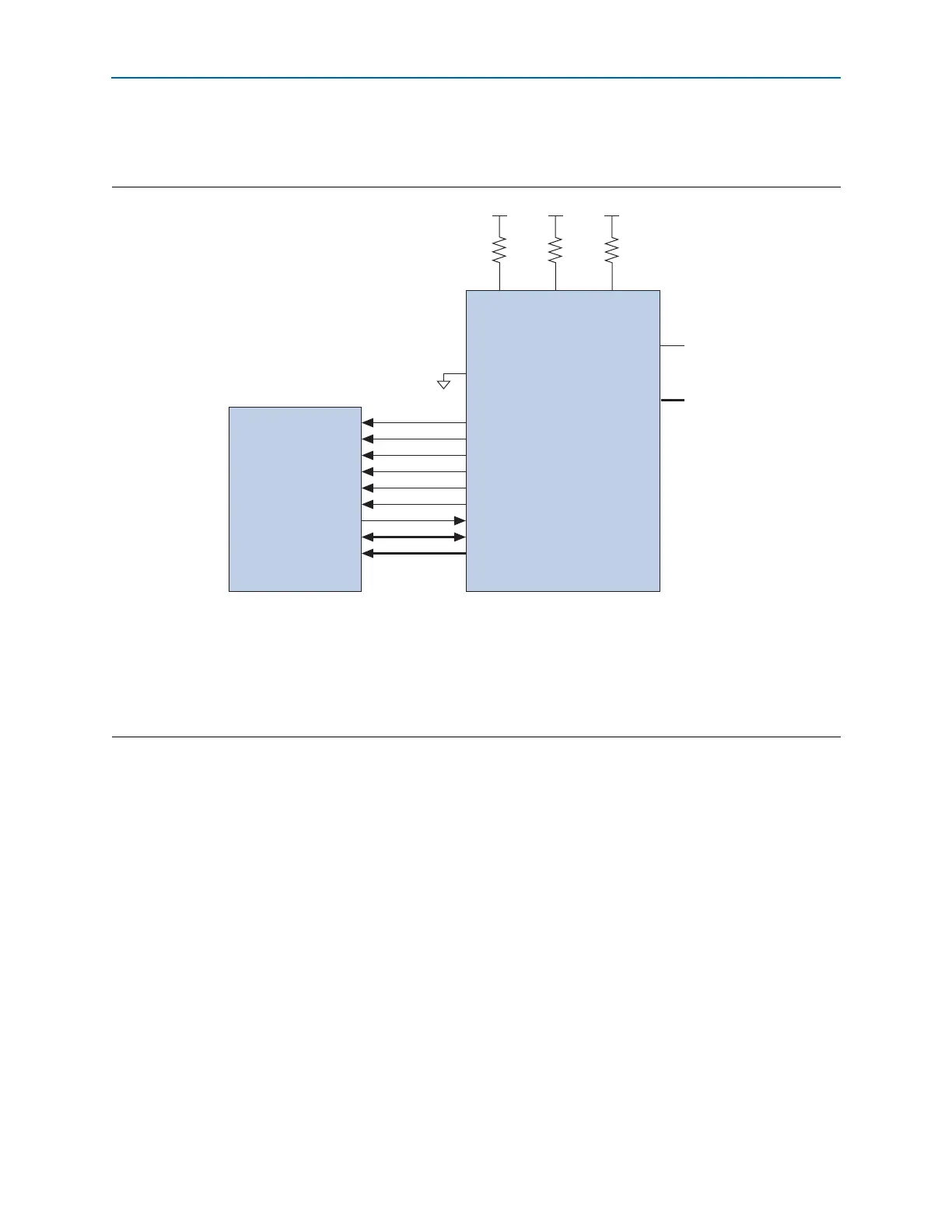
Figure 8–7 shows the interface for the Micron P30 flash memory and P33 flash
memory to the Cyclone IV E device pins.
1 To tri-state the configuration bus for AP configuration schemes, you must tie
nCE
high
and
nCONFIG
low.
1 In a single-device AP configuration, the maximum board loading and board trace
length between supported parallel flash and Cyclone IV E devices must follow the
recommendations listed in Table 8–11 on page 8–28.
1 If you use the AP configuration scheme for Cyclone IV E devices, the V
CCIO
of I/O
banks 1, 6, 7, and 8 must be 3.3, 3.0, 2.5, or 1.8 V. Altera does not recommend using the
level shifter between the Micron P30 or P33 flash and the Cyclone IV E device in the
AP configuration scheme.
Figure 8–7. Single-Device AP Configuration Using Micron P30 and P33 Flash Memory
Notes to Figure 8–7:
(1) Connect the pull-up resistors to the V
CCIO
supply of the bank in which the pin resides.
(2) The
nCEO
pin is left unconnected or used as a user I/O pin when it does not feed the
nCE
pin of another device.
(3) The
MSEL
pin settings vary for different configuration voltage standards and POR time. To connect
MSEL[3..0]
, refer to Table 8–5 on page 8–9.
Connect the
MSEL
pins directly to V
CCA
or GND.
(4) AP configuration ignores the
WAIT
signal during configuration mode. However, if you are accessing flash during user mode with user logic, you
can optionally use normal I/O to monitor the
WAIT
signal from the Micron P30 or P33 flash.
CLK
RST#
CE#
OE#
ADV#
WE#
WAIT
DQ[15:0]
A[24:1]
DCLK
nRESET
FLASH_nCE
nOE
nAVD
nWE
I/O
(4)
DATA[15..0]
PADD[23..0]
nCE
V
CCIO
(1)
V
CCIO
(1)
10k 10k
nCONFIG
nSTATUS
CONF_DONE
MSEL[3..0]
(3)
nCEO
N.C.
(2)
Cyclone IV E DeviceMicron P30/P33 Flash
GND
V
CCIO
(1)
10k